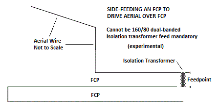
This method feeds power to an aerial wire over FCP at the loop of the FCP's three wire end instead of the junction of aerial and FCP.
With attention to where the three wire end of the FCP is placed, this allows the isolation transformer and feed coax to be at a more convenient point than directly below the aerial wire end. It also may allow the center of the FCP to be supported from an L's bend support via the vertical wire, leaving the ground space under the FCP center free of a support pole, coax etc. Other needs and possibilities seem served by this scheme, leaving that to individual installers and their circumstances.
Isolation transformer feed is mandatory. The FCP must see an isolated, balanced feed for this scheme to work. To produce a 50 ohm feed, the normal transformer for this application probably will have a turns ratio near 15 to 20.
This method cannot be used with the 160/80 dual band project. The 160/80 requires the feed in the normal place to properly switch and drive the 80 meter setting.
This concept is experimental, only being announced at this point. Modeling suggests a lower range of feed R, centering on 25 ohms, than seen at the normal feedpoint, but this has yet to be verified in actual practice. Under no circumstances adjust the lengths, spacings and dimensions of the FCP to tune the antenna.
The turns ratio of the isolation transformer can be varied to assist matching. Otherwise, remaining impedance-matching components and methods from must be applied on the shack side of the isolation transformer. We will be very interested in all comments, problems, successes and experience with Side-Feeding.