Follow guidelines below to the extent possible. They involve mechanical issues, loss reduction, other insulation issues and preventing RF carbon paths. Some installers will not be able to deal with all these, and for good reasons. Inability to comply causes loss by deploying FCP wires and their RF fields too close to lossy materials or arranges wires in a manner that weakens or defeats the FCP's zero/minimal net field trick.
Provide what separation you can, remembering that as separation increases, loss decreases and performance increases. Never change FCP dimensions to tune SWR.
You will avoid the most loss if your original installation is planned and constructed with these guidelines in mind.
Planning FCP Support, Routing and Placement
In general, orientation of the FCP to the L horizontal wire is not critical. Instead, DO orient the FCP to satisfy items below pertinent in your situation.
IF the antenna is completely in the clear, varying an FCP around the compass beneath its L will change R and X somewhat, but barely varies performance. Orient the FCP for avoidances or appearances.
Otherwise pay attention to issues below. These issues can cause large variations in radiation R and X and also reduce antenna performance by dB's.
If at all possible, suspend the FCP at a minimum height of 8 feet above ground (2.5 m), better 10 feet (3 m).
If the FCP wire folds are stacked vertically, put the fold wire with the open end on top, farthest from the ground. As with the two ends of a dipole, the open end of the FCP wire has the highest RF voltages to ground.
At the ends, if possible suspend the FCP from stiff/thick PVC support poles, or use support ropes from trees, buildings, etc. beyond the end(s). These avoid issues with other kinds of support.
In the center suspend the FCP from a stiff/thick PVC support pole or other insulating material support. Also mount the isolation transformer to this pole as well as any project box containing the isolation transformer and other circuitry, such as dual band switching. Mounting the box to insulating material will keep tracks from forming off mounting hardware inside the box.
Cap PVC pipe tops and leave the bottoms open. Or cap the bottom and drill a ⅛ inch (3 mm) drain hole to prevent them filling with water or ice. In many locations not capping both ends guarantees insects taking residence in the pipe with undesired outcomes.
Steel pipes based in concrete or driven into the ground can be used for support with some additional steps. At the upper end of the steel pipe, transition to stiff/thick PVC pipe with a 1.5 foot (0.5m) sleeved overlap, PVC on the outside of the steel. Make the PVC long enough to finish with 1.5 feet (0.5 m) of PVC pipe clearance above the steel before any aerial or FCP wire is attached or terminated.
After the steel pipe is at or cut to needed length, and before use, fill the steel pipe with wall insulation foam. Before sliding on the PVC, if the fit is not naturally tight, wrap electrical tape around the steel pipe at either end of the overlap to make it tight, wrapping both in the same direction. When sliding on the PVC pipe, twist it in the same direction as the wrap.
Drill a bolt through both pipes near the center of the overlap to secure their relative vertical positions. This bolt can also be used as a steel-based anchor point for strain relief devices on the aerial wire coming down the transformer/box.
Important: Drill a ⅛ inch (3 mm) weep hole in the side of the PVC pipe just above the steel pipe, and also just above the bottom tape wrap if wraps were used. The weep holes will prevent the PVC section from filling with water or ice.
Avoid routing the FCP parallel to and close to any kind of wall. If unavoidable, try to keep a minimum 5 foot (1.5 m) horizontal separation.
If possible do not route the FCP next to a wooden, wire or iron fence. Try to keep at least 5 feet separation. Wood will be a dielectric loss, especially when wood is older and soaks water. Wire or iron will carry lossy induced currents from RF fields not yet formed to net zero. If a fence must be used, the least amount of loss to a fence for the same separation distance is directly above the fence.
If at all possible keep a five foot (1.5 m) separation from any dielectric materials, buildings, concrete walls, fences, tree canopy above, bushes below, tree trunks, etc. In woodsy areas the best arrangement is through a ten foot (3 m) diameter "tunnel" cleared of dielectric and maintained so at least annually. Trim branches and bushes. In an unmanaged space mow weeds and miscellaneous growth to the ground and cut down unwanted saplings before they can grow up into FCP space.
Do not support an FCP with electric fence type or screw-in insulators mounted to trees or wood posts that position the wires a few inches from the wood. This arrangement has proven remarkably lossy in many instances. You can use these insulators mounted to PVC pipe.
Observe your placement area. Pick the end that you consider has the least exposure to dielectric material, farthest from the earth, etc. Put the three wire extent of the FCP in that end
Bending an FCP to Fit Severely Restrained Circumstances Where Cautions Above Cannot Be Followed Or Space Does Not Exist For a Straight Line Installation
If possible, the recommended FCP deployment is on a straight line. If the cautions above cannot be followed, one or two mild horizontal bends, less than 15 degrees, may create enough distance from loss items above. These may be anywhere on the FCP.
More drastic confining circumstances may be solved with bends illustrated left marked "YES". These sharp bends most commonly have to do with deployment along property lines, fences or walls that for a variety of reasons will not allow end-to-end linear deployment.
See top figure at left. Mentally divide the FCP's footprint into four quarters, 1 through 4 left to right. Do not bend the FCP anywhere in quarters 2 and 3. A bend at the center is particularly bad.
Acceptable bend points for an FCP are anywhere in quarter 1 or quarter 4. Bends should be 90 degrees or less off the center FCP line. Left hand or right hand bends are OK. Bends at both 1-2 and 3-4 points are acceptable and may allow a very compact deployment in extremely confined circumstances. If you are using two spacers between the center and an end support, the outer of the two spacers is a convenient bend point that does not add spacers.
Visibility Issues, Camouflage
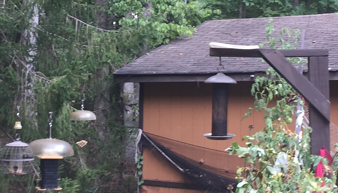
Can you see a spacer and portions of the two wire side of the FCP in this 8 megapixel photo of K2AV's back yard? They are visible in the photo if your eye can pick them out.
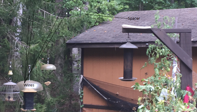
A marked copy of this photo at the bottom of this article shows the positions of the visible wires and spacer. Note how some black pointer lines nearly disappear into the dark green background.
The photo was taken outdoors next to the kitchen window to make the wires visible. A photo inside looking through the window and window screen does not show the wires. The FCP wires pass in view in front of the shed roof but the faint contrast between wire and roof in available light is beyond the capability of the camera.
When the PVC spacers were white and the copper wire was bright and reflective, the FCP was prominent, easily photographed through the window.
Visibility issues may drive a lot of decisions. At K2AV, the FCP cuts through the back yard in the kitchen window foreground a scant 25 feet away. This window views the woodsy back yard and the bird feeders, one of his wife's favorite vantage points. Separators and FCP wire were spray painted with a can of flat (not glossy) "camouflage dark brown".
An agreement between K2AV and his wife, to move it if it looked ugly from the kitchen window, worked well. His wife couldn't pick it out looking through the window and had to go outside to find it. Even when she knew where it was, she still couldn't see it through the window and window screen.
The FCP was spray-painted from a ladder after it was erected. The paint is easily scraped off the bare copper while handling the wire during erection.
Before spraying and potentially ruining spreaders, the spray paint was tested for insulation properties when dry. A layer of the paint was sprayed on a scrap piece of PVC pipe. After drying it was tested for R with a multimeter. Ohms remained in the off-scale high indication. This was further verified by full QRO operation without incident.
After that, all the various supports and boxes were sprayed the same with the "camo-brown", or painted with the flat finish dark trim color on the out-building. Now when viewing, none of it "sticks out".
All the antenna's RF measurements were exactly the same before and after the spray-painting, probably due to the very thin coat needed needed to remove reflection off bright new copper and darken the light colored PVC.
In color situations other than thick woods background, an FCP and supports may blend better if sprayed a color on one side depending on what is behind it as viewed. That could be white on one side and dark red on the other. Camouflage colors can be tested before location decisions are made.
Note that in K2AV's case, success with visibility considerations made it possible to route and construct following nearly all of the recommendations in this section, benefiting the TX signal strength.
Support Construction Issues
Support poles should be PVC pipe at the point they directly support FCP wires. Steel or wood, set in the ground or concrete to provide base support, should convert to PVC for at least the last 18 inches (0.5 m) above steel or wood vertical supports if the FCP wires are mounted close or directly to the pole.
Cap a PVC pipe that directly supports FCP wires, allowing for water exit at the bottom of the pipe. The bottom of the PVC pipe should be configured in a way which allows water exit but does not allow insects to enter. If the PVC slides over a pre-fabricated fence pole designed to be driven into the ground, leaving the bottom of the PVC pipe open and letting moisture soak into the dirt will work well.
For spacers a solid top cap and a bottom cap with a 1/8 inch (3 mm) hole drilled in the center has worked well.
Do not use electric fence wire supports that are directly mounted to tree trunks, wooden posts or fences. Dielectric material only an inch or two away from FCP wires can be very lossy. You can use these supports screwed into holes drilled in PVC pipe deployed in the clear. Some prefer these supports to threading the wire through holes drilled in the PVC.
To prevent creeping loss increases, annually maintain a ten foot (3 m) diameter tunnel around the FCP through woods and vegetation by trimming every fall.