This design reduces RF losses in the tower base and close dirt surroundings by emphasizing the Inverted L's vertical wire coupling to the top portion of the tower while reducing coupling to the lower portion. This non-constant coupling minimizes current everywhere in the tower, including the tower base. The vertical wire is supported three feet (1 m) from the tower at the top and then slopes down to the FCP with its center 13 to 15 feet (4.5-5m) from the tower. The FCP is at a minimum 10 feet (3 m) above ground. NEC 4.2 is required for evaluation to properly scale current going to ground.

The various orientations of the L's horizontal wire to the slanted vertical wire have only mildly different patterns. So the orientation of the horizontal wire should be chosen to avoid loss list issues in your situation, e.g. placing weak direction of the L for your operation and/or avoiding trees inside the bend.
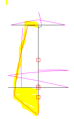
The NEC 4.2 model to the left displays the tower current without the slanted vertical wire. Instead the vertical wire is parallel to the tower, mounted 3 feet (1m) from the tower all the way. The tower current is highlighted. Note that there is far more total (integrated) current in the tower than in the L. Why is not intuitively obvious: The vertical wire and the tower (and all the conductors on the tower) are VERY tightly coupled. The slanted wire changes the nature of the coupling to tight at the top and loose at the bottom which greatly reduces the tower current.
At the bottom of the tower the RF current is 4.5 amps at 1500 watts, the highest current anywhere in the antenna wires and tower, and those 4.5 amps are being driven into lossy ground. This is true even though there is no direct RF drive to the tower.

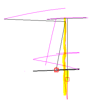
The NEC 4.2 model below left displays the tower current with the slanted L vertical wire. The tower current again is highlighted. Note that the amount of overall tower current is significantly reduced. Especially reduced is the current at the base of the tower being driven into the ground. The tower current at the ground is 1.7 amps at 1500 watts. The absolute value of the loss at the base of the tower will depend on the effective RF series loss at the base. All else kept equal, without the slanted vertical the power loss in watts will be seven times the loss with the slanted vertical, the square of 4.5/1.7.
This design supports 80/160 dual banding. It can be used with larger towers, leaving the horizontal height and the bend approximately 65 feet (20m) above ground. If improved design emerges, this section will be revised.
This table presumes the tower is topped by a medium sized 14-28 MHz multi-band beam antenna. Data below shows the shorting wire heights for various horizontal wire and tower heights. At lower heights in the table, data for the slanting vertical method demonstrates where the two methods overlap and deteriorate in the other's range.
The horizontal (or horizontal wire plus drooper wire) is always 88 feet in this table. This technique optimizes low angle results by keeping RF current dense up high on the vertical wire. See for further details.
Figures are from NEC 4.2 modeling over "average" ground. For reference, a 1/4 wave vertical over USA FCC specified commercial radial system (120 times buried AWG 4 copper 0.4 wavelength buried radials) in "average" ground produces 1.18 dBi gain.
In the table below, Tower Height, L Horiz Wire Ht, Shorting Wire Ht, are all heights above ground, not above the FCP.
| Tower | L Horiz | Shorting | Shorting | Slanting |
| Height | Wire Ht | Wire Ht | Max Gain | Max Gain |
| --Ft-(m)-- | --Ft-(m)-- | --Ft-(m)-- | dBi@Elev | dBi@Elev |
| 120 (36.6) | 100 (30.5) | 74 (22.6) | +0.16@24 | ---------- |
| 110 (33.5) | 90 (27.4) | 62 (18.9) | +0.03@25 | ---------- |
| 100 (30.5) | 80 (21.3) | 57 (17.4) | -0.11@25 | ---------- |
| 90 (27.4) | 70 (21.3) | 51 (15.5)) | -0.18@26 | ---------- |
| 80 (24.4) | 70 (21.3) | 44 (13.4) | -0.39@27 | ---------- |
| 70 (21.3) | 70 (21.3) | 39 (11.9) | -0.40@29 | -0.92@24 |
| 65 (19.8) | 65 (19.8) | 32 (9.8) | -0.56@29 | -0.76@25 |
| 60 (18.3) | 60 (18.3) | 28 (8.5) | -0.89@29 | -0.75@26 |
| 55 (16.8) | 55 (16.8) | 23 (7.0) | -1.20@29 | -0.86@27 |
| 50 (15.2) | 50 (15.2) | ---------- | ---------- | -1.05@28 |