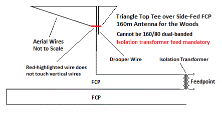
• Triangle Top Tee
over Side-Fed FCP
• 160m Antenna
for the Woods
• Cannot be 160/80
dual-banded
• Isolation transformer
feed mandatory.
←– Aerial Wires Not to Scale
←– Drooper Wire
←– Isolation Transformer
←– Red-highlighted wire does
not touch vertical wires
• Feedpoint
** ...and in forests, and in back yards that might as well be the woods.
In later text, this article contains important construction details to deal with wind, ice loads, wire motion at connection points, etc. These are methods which deal with previous exasperating breaks and tangles in woods and weather. Many of these anti-mishap methods have been in the air at K2AV over a decade without demise.This antenna mimics RF behavior of a "Tee" aerial: top load to vertical wire not intended to radiate and electrically large enough to force high RF current into the top quarter of the vertical wire.
An isolation transformer (IsoT) feeds power to the system at the FCP's three wire end loop rather than at the aerial to FCP junction.
This design addresses two large loss generating issues implementing a 160m antenna in the woods:
• "Ground" in the woods is heavily roots near the surface, poorly conductive. This makes ground radials quite lossy other than massive, dense commercial-grade. Sufficient radials, ground or elevated, are problematic in the woods. We need a simple and compact elevated counterpole, with low net RF fields at ground. For significant cause we chose the side-fed FCP for this application.
• Often the woods have no space for an inverted L. An optimal L needs a clearing. L wires over or through foliage and branches can invoke losses of 3+ dB. A "woods antenna" needs simple supports and feed using the trees, while subjecting tree foliage and ground to the smallest RF fields possible.
Two triangle folded wires, in series, at the top of the vertical wire provide top load traditionally provided by the two "Tee" wires. The red-highlighted wire is insulated and separated from the vertical wires.
The top load folding is vertical wire up to top, then far left, sloped down back past vertical wires, sloped up to far right, then nearly back to top of vertical, ending with adjustable "drooper" wire down parallel to the vertical wire.
The top load triangle uses only 50 feet (15m) total horizontal space instead of the typical 70, 100 foot plus (21m, 30m plus) for a traditional 160m Tee. This top load method increases the RF current up at the top of the vertical wire to nearly the same as at the bottom, decreasing RF loss to ground and woods.
The IsoT end of the FCP and RF power feed is at a supporting tree trunk. This removes the need to support the center of the FCP with the weight of an isolation transformer and feed coax. Instead the FCP center will be supported by end-support tension on the on the FCP and by top support tension on the aerial wires.
This support method places the aerial's vertical wire on a radius of 33 feet (10m) horizontal separation around the tree trunk. The vertical wire should clear a feed tree's foliage for all but the very broadest trees. A tree with a 66 foot (20m) foliage diameter is a very large tree.
At top of the vertical wire a triangle top load wire gives the performance of a of a traditional Tee antenna in a more compact form. It also places maximum current along the entire length of the vertical wire which considerably reduces losses to ground.
The triangle, from its ends via support ropes to two trees, supports the entire vertical wire and the center of the FCP. Contrary to the wire of an L horizontal, the support ropes can be thrown over the top of a tree for maximum height and tensioned near ground for convenience.
Isolation transformer feed is mandatory. The loop end of the short and middle wires of the FCP must behave like a balanced feedpoint for this scheme to work. The transformer action forces short and middle wire RF currents to be equal and opposite phase. Early experience with baluns in these high RF stress applications were lossy, sometimes with extreme heat, once setting a fire in W0UCE's utility shed.
Depending on FCP height and vertical wire length, EZNEC Pro/4+ models a feed R from the high teens to upper twenties. To produce a 50 ohm feed an adjustable IsoT transformer for this application should have a 16:24 center turns ratio (3 in. Regular) or 21:29 (4 in. Heavy). These two are being added to the IsoT field-adjustable section.
This method cannot be used with the 160/80 dual band project. The 160/80 requires the feed in the normal place to properly switch and drive the 80 meter setting.
Adjust the drooper wire to tune the antenna for X=0 at desired center frequency. Under no circumstances adjust the lengths, spacings and dimensions of the FCP to tune the antenna. The drooper wire may be paired with the top of the vertical wire by using a length of 450 ohm window line (e.g. Wireman™ #554). This will allow the top wires to connect to the window line with a strengthening termination, e.g. Wireman #805 or Ebay item 173794753033. The drooper side of the window line can be carefully clipped to bring the system to resonance at center.
The aerial wires must be easily lowered and pulled back up to allow carefully trimming the drooper wire for system resonance.
The turns ratio of the isolation transformer can be varied to assist matching. Otherwise, remaining impedance-matching components and methods from must be applied on the shack side of the isolation transformer. We will be very interested in all comments, problems, successes and experience with Side-Feeding.