We have combined and rewritten previously separate "Designing" and "Placing" inverted L articles to improve reading flow and avoid effort updating considerable duplicate content. We include a descriptive index with links to article Section and Subsection text to quickly find or return to material of interest.
Illustration Title
For international readers with browsers using auto-translation,
we are copying English text embedded in illustration graphics
out to plain HTML text where auto-translators can see it.
The illustration's translatable title and text
are boxed like this following the illustration.
Translation cannot be done inside the graphics, as in a PDF,
because a short phrase in English may properly translate
to a graphically longer phrase, covering up illustration.
Graphics text copied into HTML will be added over time,
starting with important illustrations
in most frequently read articles.
This article and others on this web site may use the term "counterpole". This refers universally to any "radial" system or counterpoise design, including unknown or unintended but in-fact counterpole elements. "Aerial" refers to radiating parts of the antenna system, intended, unintended, or unavoidable. "Antenna system" includes aerial, counterpole, antenna located coax and matching devices. See "Definition of Antenna System Aerial and Counterpole"
Though this article on low-band, roughly quarter wave inverted L's is part of a web site on the FCP, the content below applies to L's regardless of what may constitute the L's counterpole. Most "I have a problem" correspondence after erecting an L over FCP were not about the FCP itself. No longer swamped by counterpole RF losses, an L can exhibit surprising characteristics and complexity.
• Section
or
• Subsection
direct link to indexed text. When visually scanning article text, matching
• Section Title
and
• Subsection Title
banners separate article text for ease in location.
Since publishing the FCP, installers have reported a surprising number of issues bearing on design and placement, most solved. We urge you to learn these. Some may not apply to you. But deal with all that do apply, however you can. Otherwise, you can leave unremedied losses with quite workable solutions, all worth parts of dBs and sometimes dBs. Unremedied, the sum of these losses reduces your transmitted signal before you ever encounter propagation.
For some, the content in this article might seem overwhelming, far too much to read beginning to end. But we urge you to take time to read the index. Then you can choose your subjects to read, and later return to a needed specific subject. Good Reading and Good Luck getting on the band !!
There have always been posts on list servers telling a newcomer to just throw up any antenna, put down a few radials and get on the air, have some fun, get started. It's understandable why they say that. For some 160m operating, the path loss is low enough at the time that even a very low actual radiated power can accomplish a satisfying QSO, even with DX. Ah, sweet success, you're on 160. But...
What if the antenna system has 8 dB loss and 100 watts from the transmitter only radiates an effective power of 15 watts? It's easy for a "just thrown up" 160m antenna to be that way. Your chances of a sweet first QSO just got reduced. Knowing the material on this web site in advance, one might easily improve the effectiveness of that first 160m antenna attempt by avoiding known dB-killers.
From over ten years of L/FCP projects modifying existing 160m setups...
Many times in recent years, the fix total of a surprising number of RF loss items was validated by an equally surprising overall RBN improvement. More so, ample improvements in contest scores, 160m DXCC counts, QSO range, etc, satisfied why they undertook those dB improvements in the first place.
Replacing a deficient on-ground counterpole with an FCP often produced an overall 5-7 dB improvement. Mostly, that's not because the FCP was so great, but the replaced prior counterpole really was that bad. See A Remarkable Story below for a 1970's early warning about possible grotesquely huge ground losses.
An FCP installation with careful attention to the other loss remediations has produced 8-10 dB, up to a rare 12 dB, roughly the same as adding an amplifier. A few notable larger improvements included an L over FCP replacing a seriously inferior aerial wire and extremely inferior counterpole. Other quite large improvements occurred when the smaller FCP as counterpole enabled a much better aerial wire placement on the property that avoided severe dielectric losses at the old placement.
Common space-saver vertical antennas concentrate RF current and fields near the ground, with maximum lossy coupling to ground, even with a good counterpole.
A theoretical lossless space-saver vertical has very low actual radiation resistance (Rrad) on the lower bands, frequently single digits. For some of these actual antennas done very efficiently, resistance at aerial-counterpole junction with no impedance matching (Rant) could be 10Ω with a 10 kHz 2:1 SWR bandwidth. The various loss factors invoked appear at the antenna feed point as effective series loss resistance (Rloss). The feed resistance (Rfeed), as seen by the antenna end of the feed coax, is the same as Rant if there is no impedance matching device or non-one-to-one transformer in use.
This gives the equation we need to have in mind every time we look at the R value (Rant) displayed on our antenna analyzer at the aerial/counterpole feedpoint:
With a high Rant due to aerial wire(s) heavily coupling ground,
Rloss can be the majority of Rant .
A poor counterpole further increases that Rloss .
Some commercial ham vertical antenna products deliberately count on a poor counterpole to add Rloss to the antenna system. They do this to bring Rant up to 50 ohms, reducing or eliminating matching devices, reducing manufacturing cost. Since the loss increases bandwidth, it also reduces customer complaints about SWR and bandwidth. They already know how requiring a truly adequate radial field cuts down on sales.
Forcing low angle RF to exit the locale through neighborhood trees and buildings, a short vertical's low to the ground RF takeoff adds far field RF loss. This far field loss does not signal presence by changing feed Z or SWR, but is just as adept reducing our signals at the distant end. An antenna change minimizing RF passing through neighborhood dielectric clutter will improve signal strength at the distant end.
K2AV tells a 1970's 80m traffic net story about a young member of the New York State CW Net with impressive CW operating skills. The young man was still in high school, living with his parents on a sub-quarter-acre lot in an old, completely built-up section of Rockland County, NY, across the Hudson River from New York City. His 80m aerial was a 25 foot (8m) vertical aluminum mast with a base loading coil.
The antenna's counterpole was its ground mount pipe driven into the earth, plus a few irregular wander-about on-ground "radials," plus the outside of the shield of the feed coax and whatever was connected to that. His Johnson Ranger's single 6146 final ran 75 watts input, 50 watts out to his loaded short vertical.
The young man's excellent operating was not matched by his signal strength, consistently markedly weaker than other low power stations on the net. K2AV lived only 20 miles (32 km) northeast, across the Hudson River in Putnam County, NY. But often K2AV could barely copy the young man. Sympathy, sore ears, elmering instincts, and intense curiosity about why so weak, all drove K2AV to offer help. Offer accepted.
K2AV's 80m end-fed half-wave L (EFHWL) was easily his best ever 80m wire. With that and 650W out from four 811A's, he worked difficult 80m NTS traffic schedules into the western states. At times, other eastern QRO stations could not finish these schedules, making them hard to staff.
This in mind, noting two suitable support trees at the Rockland County site, they agreed on an 80EFHWL.
Next free Saturday they replaced the mast with the EFHWL. To match its high feed impedance, they made a low power tapped parallel L/C network from junk box parts. They put it inside the window out of the weather, next to the operating position, easily reached to tune. Then K2AV went home to hear the results.
Back then there was no Reverse Beacon Network (RBN), no PC's, no internet to feed dB data to our modern instant analysis apps. We only knew what people said when they heard the difference.
On the net, words for the increase were "Wow", "Very large", "Two or three S-units", etc. The change was enormous. The young man could now pass traffic to the eastern US and eastern Canada with 50W to his new EFHWL. No-copy in Florida had improved to 569's, poor copy in eastern Canada to 579's. A too frequent 459 from K2AV just across the Hudson River improved to 589. For 459 analysis see §§ below.
We didn't know then why such a huge improvement. Now we know the EFHWL demonstrates proven RF loss reduction strategies: Make the counterpole efficient. Or make it of little consequence with a high voltage, low current, high impedance feedpoint. Move maximum antenna current away from ground, high in the antenna if possible. These and other changes can produce startling performance improvements.
An 80EFHWL has maximum 80m RF current up at the bend in the L, nowhere near dirt, with much higher average takeoff height, reducing RF losses in local trees and ground clutter. The end feed to the halfwave is high impedance with far less current near ground or in the counterpole, sharply reducing ground loss.
So that kind of loss certainly is possible, but can be fixed, OR avoided in the first place.
80EFHWL performance led to this web site's dual-banding project 160/80 on One Inverted L over FCP. What if we take an existing 160m quarter wave (¼λ) L over FCP and add excellent 80m local and DX performance to those existing wires? Relays switch the FCP counterpole to 80m and engage a tapped parallel L/C circuit for matching high Z feed. The FCP counterpole up 10 feet and the current maximum near the L's bend eliminate much ground loss incurred by ground-based 80m ¼λ and shorter verticals.
§§ The acute change in signal to K2AV, only 20 miles (32 km) away, suggests the old antenna had very weak ground wave and no near vertical (NVIS) propagation. Low through middle-high angle takeoff would skip over K2AV in any event. At least eight loss and antenna pattern factors contributed to RST 459:
(1) The old antenna had no effective radials, producing an extremely lossy counterpole. This weakened ground wave and all angles of sky wave, including any NVIS high angle sky wave to K2AV.
(2) A short vertical's elevation pattern significantly weakens above 60°, further reducing NVIS to K2AV.
(3) The multiple ridge and deep valley terrain between them abnormally reduced ground wave. This permanent terrain-based loss added to the effect of other loss factors upon ground wave to K2AV.
(4) The antenna's highest RF current being right at ground increased dielectric and induced I²R loss in the ground and local clutter. This further weakened ground wave and all sky wave takeoff angles.
(5) A 1/10λ vertical mast's RF current (I) near to, and RF fields in ground, will triple the losses of a similarly placed ¼λ vertical. With Ploss proportional to I², ground losses in watts were ~10 times the ¼λ.
(6) With higher I, a given telescoping tubing joint resistance adds 10 times the I²R joint loss as in a ¼λ.
(7) Ten feet separated the mast from three large RF-lossy dielectric globs: the house and a pair of two foot (61cm) thick tree trunks. The short mast concentrated RF fields in these, further reducing the signal.
(8) The mast's base resonating coil was made from solid copper AWG 18, wound on a paraffin-boiled 2 inch (51mm) cardboard mailing tube. That was lossy but a common and affordable design for that decade.
In the list above, every item except (2) and (3) reduced his signal strength at all receiving stations.
The new EFHWL replaced the problematic 1/10λ aluminum mast with a ½λ 135 foot (41m) inverted L wire. This moved the RF current maximum up to the L's bend at tree-top height. Dielectric loss to the house was reduced to less than 5% previous level. Dielectric loss to the trees was roughly halved. The EFHWL's pattern has no high angle null, restoring NVIS. Changing to a high impedance feedpoint reduced losses at ground to a small fraction of previous levels. All these improved ground wave and NVIS toward K2AV.
To contrast the 1970's aluminum mast and surroundings, how would we design and place a modern, base loaded 25 foot (7.6m) 3.5 MHz mast, with least possible loss as the most important design goal?
At 1500W these steps improve power handling of QRO 20+ amps RF current on a 1/10λ mast. Running 5W and 100W, these steps "only" remove loss, which improves signal-to-noise ratios at the distant end. For performance reasons, LP and especially QRP need QRO rated components as much as QRO.
The 80m remarkable remedied loss story above illustrates sharply reduced performance of a young man's short 80m vertical antenna system. It was heavily loaded down with ground and dielectric RF loss, effectively reducing his transmitter's fifty watts output to an estimated one watt radiated. This suggests 15-20 dB losses to anyone receiving the young man's signal. There were worse losses toward K2AV.
Laws of physics involved tell us, that versus 80m, 160m has the potential for even larger RF losses.
In 160m contests with good conditions and the band fully open, K2AV notes differences between known 100W contest signals from Wisconsin/Illinois/Indiana (W/I/I). These routinely range from 5 dB over S9 (W9RE) down to what would be S4 or lower if the band noise was gone. That's a 30 (thirty) dB spread on his calibrated K3's 5 dB per S-unit display. The weaker stations include some QRO signals below S9.
These weaker W/I/I stations are mid to high angle paths to K2AV, so NVIS and low angle problems at a transmitting site would not make any difference. These weaker signals remain weak relative to other W/I/I signals regardless of the antenna being used to receive. They remain weak whether listening vertically or horizontally polarized. They are simply weak, implying heavy resistive losses in their antenna systems.
Why are 160 meter antenna system losses usually worse than 80m, and much worse than 40m?
The difference starts with a normal superiority of vertical polarization for best performance at low (LF) and medium (MF) radio frequencies, which includes 160m. This pushes us toward use of vertical antenna structures and wires with the unavoidable ground involvements that come with them.
Looking at vertically polarized antennas, there is the vertical ½λ, with the least natural involvement with ground loss. In the 1950's, certain USA clear channel AM broadcast stations put up enormous ½λ towers on high spots to increase coverage. But a 250+ foot (75m+) vertical dipole with high voltage base insulation is far beyond most means and sure to stir up HOA complaints. This moves us to consider ¼λ designs with their unavoidable ground and loss predicament.
But even the ¼λ's 128 feet (39m) is too much for many. There are shorter alternatives: top loading, base loading, T's, inverted L's, slopers, gamma matching short towers, etc. Unfortunately these all require someplace to store and retrieve the full transmitting current charge coming from the feed coax shield.
If a provided counterpole is not excellent, the antenna voltages will force what power it can into it and find the ugly counterpole to stuff the rest, dividing power between two lossy alternatives.
If the provided counterpole has a deliberate feed impedance (Z=R+jX) not near zero (e.g. FCP), the antenna system will create the ugly counterpole and divide the power, UNLESS the antenna system is forced to use only the intended counterpole. An isolation transformer, one secondary lead to the aerial wire(s), the other to the counterpole, is the "brick wall" solution to blocking a path to an ugly counterpole.
An ugly counterpole with a very low feed impedance will require blocking, even if an excellent intended counterpole has almost-zero feed impedance. Otherwise serious loss can occur when operating a resonant counterpole away from its resonant frequency.
To block paths to ugly counterpoles, see units specifically designed for low band QRP, LP and QRO:
An ugly counterpole will use the outside of a coax shield and any connected grounding wires or rods. It will also use any conductors connected or capacitively coupled to the coax shield, including earth below or around it. These ugly counterpoles invoke many RF power loss issues found in the Loss List.
Worse, to radiate the same power as the dipole, the half-sized single ¼λ and counterpole carry twice the RF current as the ½λ. Since Ploss=I²Rloss , a loss issue in a ¼λ can cause four times the power loss in watts as the same issue in a ½λ. What doesn't bother a ½λ too much can be trouble in the ¼λ vertical.
Earth (soil) and local dielectric material are a great RF energy soaking sponge. The formula for losses from a counterpole element in watts is I² times the sum of
Total loss from linear horizontal counterpole elements are mostly proportional to length. Increased length increases the amount of very near conductive and dielectric materials. Uncorroded RF wire loss by itself is almost exactly proportional to length and frequency, but is rarely the controlling issue on 160, especially with bare, solid AWG 14 and thicker. Thin wires, wires with corroded insulation, stranded wires holding water between threads are all easily capable of significantly increasing simple wire RF resistance.
Significant losses occur when sparse parallel-to-ground counterpole wires induce RF fields in a span of ground underneath. If a 40m ¼λ wire induces RF fields in an N foot long span, an 80m ¼λ wire induces RF fields in a 2 x N foot span and a 160m ¼λ wire induces RF fields in a 4 x N foot span. The induced ground current loss from a radials counterpole is roughly proportional to the length of the span of dirt being induced.
Dielectric loss is the summation of dielectric heating of molecules in the vicinity of the wire. The size of the vicinity is larger for a longer wire. Even if the only dielectric material close to the wire is dirt, then the dielectric loss is proportional to the wire length. All three major elements of loss from a horizontal counterpole wire are in some way proportional to length.
So induced loss in watts for the 160m version will be roughly four times the loss at 40m. This is why so many good radials are needed for 160m, to divide that increasing resistance loss by the number of radials.
The size of 160m ¼λ radials for verticals and inverted L's exposes the installer to everything discouraging an efficient radial-based counterpole: How to fit in limited lot space; Limited financial resources for mile(s) of expensive copper wire for radials; Limited time and limited ability for the physical exertion required to bury or fasten down radials, and more. One way or another they all push an installer to attempt less than a full size, dense, and uniform all around, efficient, commercial-quality, gold standard radial field.
We understand, fully sympathize with issues involved, pain of construction, etc. But the unsympathetic, brutal physics involved, particularly on 160m, means not installing the gold standard radial system or elevated equivalent costs dBs. If we can't do the gold standard, let's carefully choose losses we live with, and minimize or eliminate the rest. Particularly on 160m, let's at least consider an FCP before we decide.
Beyond inverse frequency-proportional losses, miscellaneous loss items can afflict nearly anyone. There is a "Loss List" of these on this web site: The Loss List - Your Shrinking RF & Fixes. All the items in the Loss List have been found at one or the other correspondent's QTH, often with a surprising number of items found at one QTH. Most were avoidable or repairable. To not hunt for these Loss List items at your QTH, not make sure you are unaffected, or not repair or avoid them, could cost many dB.
Converting to an FCP from a constrained, irregular, sparse counterpole, plus various loss remediations (referred to as FCP+ on this web site) has now and then harvested a measured 12 dB, nearly always 5-7 dB or more. Doing the work is often like buying an amplifier for your 100 watt transceiver. 100 watts plus 7 dB of antenna system remedy is like adding a 500 watt amp, 10 dB like adding a kW amp and 12 dB is like adding a 1.5 kW amp. Already have a 1.5 kW amp? Then 12 dB of repair is like sending 22.5 kW down the coax to the old antenna system before the repair.
Starting with the Loss List, you may find you have loss items on the list that you cannot avoid or repair. A common item is a tree or a large dielectric mass, such as a dwelling, inside the bend of an existing or planned L. You may not have the space or support points to avoid it. The only possible aerial wire support may place your most needed direction in a weak RF pattern sector. Or the only remedy and placement may violate household and/or neighborhood politics. Imagination and negotiation may be required, with the risk of failure. K2AV has been through that.
K2AV's L has the apartment/garage segment of the dwelling inside the bend, but that's where it has to be. He knows he's taking a hit for that, but he worked the entire loss list and avoided or repaired all else on the list. Those recovered dB fragments return increased scores and better signals at the edges of propagation.
OK. I have read the Loss List. I have begun executing a program of removing, reducing or repairing loss issues. But I also want to see a nice SWR. And it definitely looks like the SWR is getting worse. Worse than that, the SWR bandwidth seems to narrow after every fix. Shouldn't I work on the SWR as I go?
You almost certainly are getting those SWR changes, but the answer is definitely "NO" to working on SWR as you go. See this warning from the article on tuning up an antenna over an FCP.
Keep fixing the losses you intend to fix and leave the SWR adjustment, AKA "antenna matching", until last. Remember that every loss removed immediately improves your antenna system's performance. For the time being, to enjoy the performance increase, use that transceiver or amp auto-tuner, or a matchbox to deal with SWR. Get your loss work done and then worry about fixing SWR out at the antenna.
Tuning after repair is covered in detail in Taming/Tuning the Exasperating Inv L & other Aerials over an FCP. One of the first things the article says is to complete all the loss removal and other repairs before you start the Taming/Tuning.
First, abject apologies for introducing math. Many could easily do without it. Some hate it. Others need it as a trust factor. We hope it is useful for some. You can skip the math and jump to to the next subsection.
Before remediation, losses can seriously reduce 160m antenna performance. But how can we analyze the loss and predict the change in loss, and it's effect on antenna SWR curves? We will use the popular and now free EZNEC antenna modeling program to show what changes pattern, amplitudes and SWR curves.
EZNEC uses input data and program code to account for wire losses and always-present basic ground losses in presumed flat, open fields. It cannot account for unknown land clutter or losses that are by nature poorly defined or undefinable.
To solve this problem, a lump sum can be added to the model in the form of a miscellaneous loss effective series resistance (Rmloss) inserted at the feedpoint using the EZNEC "load" device. This adds to the computed radiation resistance (Rrad) from the antenna elements design and the computed effective series resistance (Rcloss) from ground characteristics and conductor loss. These add to create the antenna's presented pre-isolation-transformer (pre-IsoT) feedpoint resistance (Rant) :
Taking the formula for impedance:
and substituting the definition of Rant , we get:
The frequency scan EZNEC uses to make an SWR curve creates a significant variation in jXant and a smaller variation in Rrad across the range. In turn, these significantly vary Zant across the frequency scan. Rcloss will change only slightly across the frequency scan, and Rmloss is a constant. Varying the value of Rmloss does not change Rrad and jXant frequency scans.
If Rmloss is small, an efficient antenna, then Rant varies more percentagewise across the frequency scan. jXant change with frequency adds to the variation seen in Zant and the SWR meter in the shack.
For real world in-the-shack SWR appearance, the table below takes into account matching networks installed to match the antenna's Zant to 50Ω coax. If Rant was a nice low, efficient 31Ω, something would be done to raise that to 50 ohms. What if the Rant was a not-so-efficient 41Ω? The owner probably matched the sum of radiation and loss to 50Ω coax. Rows in the table below assume the owner has done that. The Ω:Ω ratio needed for this matching is listed in the table.
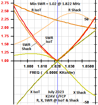
EZNEC generated the table values below. We chose program values with Rmloss set to zero to generate a close likeness of K2AV's Jul 2023 summer L/FCP. K2AV Jul 2023 readings appear at the head of the table with further explanation at **. The K2AV Dec 2022 values show the normal winter/summer change.
The table varies Rmloss from zero to 65 ohms using an EZNEC "load" element. The table reports progressive changes: reductions in antenna pattern maximum dBi, increases in watts wasted from 1.5 kw applied to the antenna feed, and gradual broadening of SWR bandwidth.
The pre-IsoT Rant at Xant=0 is matched to 50Ω at IsoT output using the EZNEC transformer device and varying its input-output ratio. The table lists the ohms-to-ohms transformer ratio used for each row. Max gain degrees elevation always computed 34° and the X=0 frequency always computed 1829 kHz, therefore neither value is listed.
| Effect | Xfmr | Max | -dB | Low | Low | High | High | 1.5:1 | 2:1 | Watts |
|---|---|---|---|---|---|---|---|---|---|---|
| Ser Loss | Ratio | Gain | vs 0Ω | 2.0:1 | 1.5:1 | 1.5:1 | 2.0:1 | SWR | SWR | Loss @ |
| Rmloss | Ω:Ω | dBi | Rmloss | Freq | Freq | Freq | Freq | BW | BW | 1.5kW |
| K2AV: | 29:45 | (Dec | 2022) | 1805 | 1814 | 1837 | 1845 | 23 | 40 | * |
| 32:49 | (Jul | 2023) | 1799 | 1809 | 1835 | 1845 | 26 | 46 | ** | |
| EZNEC: | ||||||||||
| 0 | 31:50 | -1.08 | - | 1807 | 1816 | 1841 | 1850 | 25 | 45 | 0 W |
| 5 | 36:50 | -1.72 | -0.64 | 1804 | 1814 | 1843 | 1854 | 29 | 50 | -206 W |
| 10 | 41:50 | -2.29 | -1.21 | 1801 | 1812 | 1845 | 1857 | 33 | 56 | -362 W |
| 15 | 46:50 | -2.78 | -1.70 | 1797 | 1810 | 1847 | 1861 | 37 | 64 | -485 W |
| 20 | 51:50 | -3.23 | -2.15 | 1794 | 1808 | 1849 | 1864 | 41 | 70 | -585 W |
| 65 | 96:50 | -5.97 | -4.89 | 1763 | 1791 | 1867 | 1895 | 76 | 132 | -1013 W |
EZNEC ground characteristics were set to (.002,12). EZNEC runs producing the table were version Pro/4+ V7, real ground, extended accuracy, NEC-4D engine.
The 20Ω Rloss produces a comfortable 51Ω Rant . The 65Ω Rloss value models to 5 dB worth of loss problems in the antenna. A 5 dB loss remedy, or 6 or 7, roughly an S unit improvement, shows up at a lot of L/FCP projects in before and after RBN data comparisons.
Increasing a frequency-constant Rloss added to the varying Rrad lowers the percentage that Zant changes for a given frequency change. The SWR meter and our hard-to-please TX and amp finals are watching Zant vary. They have no idea what component R's are in the Zant The sneaky included Rmloss allows us to feel good about the SWR, but quietly reduces signal strength at the distant location.
Conversely when that Rmloss is reduced or removed, the SWR bandwidth narrows. Some have kept their Rmloss rather than deal with narrower bandwidth. That's their choice. But it has a watts price tag whose payment can not be refused.
Repeating ourselves, to do loss remediation with the least cost and effort, tuning needs to wait until remediation is accomplished. Or if you must do it in separated stages, you may have to redo tuning/matching at every stage to reconstruct the comfortable 50 ohms resistive to match the coax.
* K2AV December 2022 values are those following encroaching tree removal and well into no-leaf no-sap season. The next sub-section below, "A K2AV Example of loss removal narrowing SWR bandwidth," details this loss mitigation project and its effects.
** While resonant frequencies differ, the EZNEC Rmloss = 0 table row SWR BW data are quite close to the measured K2AV July 2023 row. In the summertime, resonance can be a wandering 4 to 8 kHz lower than the fairly stable winter no-leaves, no-sap resonance.
The graph shows K2AV's R,X,SWR curve sets at the isolation transformer (IsoT) and at the antenna switch at the operating position. The shack SWR curve is just slightly changed from the IsoT, due to very low loss in the feed coax. A mix of RG115, LDF4-50A and RG400 are a little less than an electrical ¼λ. Note the near-complete inversion of the R and X vs. frequency curves.
In early November 2022 K2AV had tree removal done to deal with roots tearing up his asphalt driveway. While the tree professionals had their crane and crew on site, K2AV also had two 80 foot (24m) oaks removed in the back which were growing into the clear space containing his Trident L over FCP.
The trees on both sides of the far-end half of the L horizontal wire now entangled the L during high winds. Subsequent antenna-to-tree arcing faulted his KPA1500 and 8410 amplifiers. Moreover, a lot of the foliage extended inside the L's bend, in the 6 to 8 times higher RF field zone, adding RF loss to amp-faulting.
It was clear that if the two trees grew further, the property's last site for a 160m L/FCP would be lost. Fortunately, this was a point K2AV's wife clearly understood. Other than carefully negotiated exceptions, the property remains heavily wooded per decades-old agreed-upon family policy.
With the two trees gone, and after leaves and sap were finally down, all antenna matching done, winter center-frequency R at the feedpoint (Rant) decreased from recent years' winter 32Ω to 29Ω.
At tree removal, without changing wire length, resonance went from 1822 to 1833 kHz. Horizontal wire lengthening later lowered it to 1825. Beginning of no-leaves, no-sap season dropped it to the desired 1820 kHz. 1.5:1 SWR bandwidth dropped to 23 kHz, 2:1 dropped to 40 kHz and 3:1 dropped to 64 kHz. The small adjustments to horizontal length made for resonance did not change SWR bandwidth.
K2AV's response, "Ouch on the bandwidth, but I'll take a dB and no more amp faults as a reward."
Removal did appear to bump-up RBN. But the antenna had to be down and pulled away for them to work. That, tree pro scheduling, and changing weather prevented before and after field intensity measurements.
At the low current, high voltage end of the L, we can get enough capacitive current to local foliage and clutter to make the L horizontal seem longer than the actual wire length. Consider the far end of the horizontal wire to be one plate of the capacitor, and foliage, etc, the other plate. That would seem a very small capacitor. But high voltage at the end of the wire overcomes small capacitance. Even a very low resulting RF current across this "capacitor" extends the effective RF length of the wire.
Removing two large oak trees would have greatly reduced the capacitance of aerial wire end to local dielectric/conductive material. This would have shortened the effective length of the horizontal, accounting for the tree removal's immediate 1.822 to 1.833 MHz resonance change.
After the tree removal, the horizontal length and IsoT turns ratio both needed dry-weather, no-leaf, no-sap adjustment to return coax-side IsoT to 50+j0 at 1.822 MHz. As this L/FCP was a 160/80/40m Trident L, the 80m matching taps also needed redoing. 40m taps moved only slightly.
The post-tree-removal early November 2022 SWR bandwidth numbers did not change with the late December 2022 resonance and IsoT turns ratio adjustments. The hard-to-prove gut suspicion was that the tree removal reduced the seasonal change.
At times K2AV gets a little bummed with all the switching to use the 160 L/FCP on the entire 160, 80, and 40 meter bands. Sanity returns when he remembers he is getting premium contest grade overall efficiency and complete band coverage on a residential lot that does not support that with ordinary simple antennas. For over 30 years he has been happy where he's living and he isn't moving. That pays for the complexity.
K2AV's winter 160m bandwidth is centered at 1.822 Mhz. 1.5:1 SWR bandwidth is 23 kHz, 2:1 is 40 kHz, 3:1 is 64 kHz. The K3 and KPA1500 auto-tuners easily handle 3:1 at 1.854 MHz to avoid automatic power reduction. The 1.5:1 range of 1.811-34 has the KPA1500 in bypass mode all night most nights. But during serious QRO contest weekends, the incoming 4:1 SWR up at 1.866 MHz increases heat stress on autotuner components and faults the KPA1500. The incoming SWR fault level could be set higher in the KPA1500, except for K2AV's nervously imagined smell of smoke. He has had his share of blowing things up.
To deal with his late-in-life range anxiety over blowing up auto-tuner components and amplifier finals, K2AV added a 160 "B" range. Selecting 160B inserts a high power 3500ρf capacitance between the IsoT and aerial wire, moving resonance up to 1.847 MHz. The 1.5:1 SWR range is 1835-59 Mhz, 2:1 is 1827-68 MHz and 3:1 occurs at 1.883 MHz.
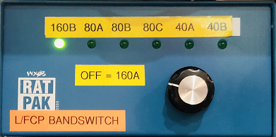
The RatPak control box at left switches bands, band segments, and FCP state (160m or 80/40m) for his three-band "Trident L" over FCP. No light lit (switch to a null position or no power to the box) selects "160A", all L/FCP relays de-energized.
The "160A" and "160B" ranges together give a 1.5:1 "W" curve 1.811-1.859 MHz with center peak at 1.835. This covers nearly all K2AV's 160m operating, with KPA1500 auto-tuner mostly in bypass.
The combined easily-auto-tuned 2:1 range of 1.802-68 covers CW contests with contestants found from band edge to 1.870. It covers K2AV's informal SSB operation in the 1850's and 60's. The upper range center at 1.847 keeps the KPA1500 in tuner bypass with final transistor current at minimum for FT4/8's heavy duty cycle. It also keeps the AL1200's 3CX1200A7, 8410's 4CX1000As and the "Big Momma" 3-1000Z happy for 160m operation at times the big tube amps have to fill in.
The "160B" series capacitor (or capacitor array) needs to be sized for amplifier level RF current. The non-energized center frequency at 1.822 MHz is done with the normally closed contacts of a single pole relay across the capacitor. If K2AV was mostly operating FT4/8, he could set the non-energized center frequency to 1.847 by using the normally open contacts on the relay.
Only one contest a year (CQ 160 SSB) has run frequencies above 1.870 MHz. Above 1.870 the 160B range is extended in the shack by combining auto-tune and his ATR-30 manual tuner. A single ATR-30 inductance setting works for the entire range above 1.870, making manual tuning a quick, two-knob, by the numbers operation. Even using the big tube amplifiers, the by-the-numbers works well enough tweaking the amplifier tuning capacitor.
Many readers will see this section as trivial or unnecessary. They have already settled these issues and can easily map an antenna's published RF pattern plot to their own situation. Such enlightened readers may skip down to RF Pattern Orientation of an Inverted L.
However, as we discovered, some correspondents had never heard of this, some had never thought it through on the low bands. Once aware, they saw their location very differently. Some had already erected their L, unintentionally reversed from or considerably off optimum for their location and operating. To avoid their considerable effort to redo their L, we include the following material.
If you are going to do a 160-80m or 160-80-40m (Trident L) FCP project, then you need to include your operations on all the targeted bands in this exercise.
Make a list of your operating on this band(s). Include any nets, scheduled ragchews with a ham friend or relative, DX chasing, contests, whatever. Make the list, so if there are trade-offs to be made, you will have all your operating in mind when you decide. It's easy to forget some well-enjoyed aspect of your operating until after you have erected the antenna.
First, create an azimuthal-equidistance map for your location. Click here for NS6T's excellent azimuthal map generator. Note his help links right of "Location" and "Distance" entry boxes.
Second, using the azimuthal map, add the great circle bearing to each operating destination.
The Trident L is designed for 40m to have the same pattern maximum and minimum as the 160m pattern. 80m is fairly omni, but still with the same directions for mild maximum and minimum. So this exercise serves all three bands.
At K2AV, in the Southeast US, most operating is well-covered by an L/FCP with its pattern maximum North. Here is the NS6T Azimuthal-Equidistant map generated for K2AV, Apex, NC, USA, FM05nr.
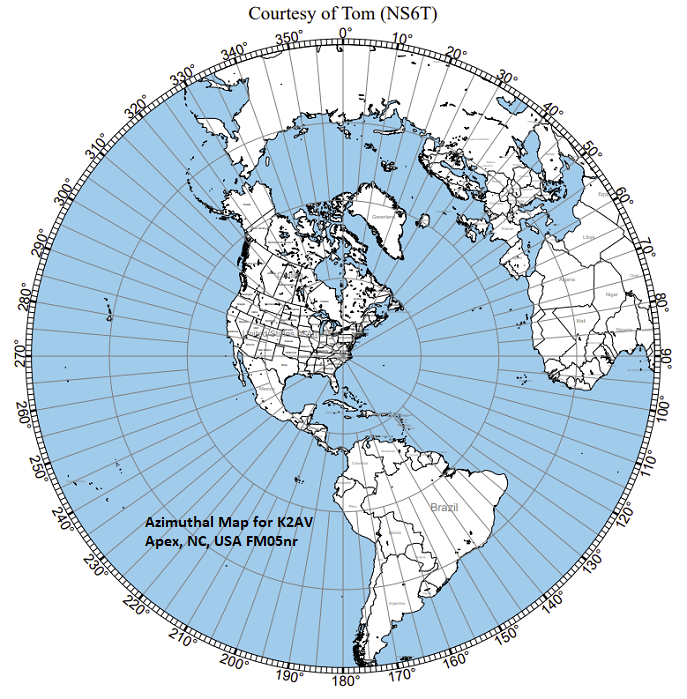
At K2AV major 160m contests with DX participation (CQ 160's, ARRL 160, Stew Perry's) require the 20° via 45° to 70° EU DX directions. West coast, far NW multipliers in CQ, ARRL, and especially NW 7 and 8 point contacts in Stew Perry, require coverage 270° via 300° to 330°. Caribbean, Central America and northern South America are NVIS or mid-high takeoff angles on an L oriented for 360° max. LU is tough, but if heard is usually worked QRO regardless of being weak side on the Inverted L pattern.
This indicates south as least important direction for low-mid-takeoff angles. K2AV's L pattern north max will have the south down 3 to 4 dB. But with a possible northern 5-12 dB improvement over a prior lossy antenna system, that's still a southern improvement of 2-8 dB in the pattern minimum.
On this web site we use terms like "inside the bend", "toward the bend". Confusion in early correspondence exposed conflicting ways to describe inverted L directions and dimensions. Some read our description, then put up their L with their most-desired direction at pattern minimum. They simply would not have used those terms to describe the desired result. So we had to pick one set of terms to use and explain. So, with apologies to those with other perfectly reasonable verbal schemes, here are pictorial definitions for the inverted L terms used in this document.
Inverted L Definition of Directions
Sighting along the horizontal wire, viewed from its center
<== Toward the End Toward the Bend ==>
<== Weakest Direction Inside the Bend Best Direction ==>
Any Counterpoise In Front of the Bend
The low angle azimuth pattern of an inverted L is best described as an off-center circle favoring the direction looking toward the bend. On flat land it has a mild disadvantage looking toward the end.
In the inverted L plots, the azimuth elevation (takeoff angle) is 20 degrees. The inverted L with "average" ground underneath has a front-to-back of 1.5 dB. With very poor ground underneath, the front-to-back can be as much as 3.5 dB.
Total Field Inverted L Average Ground
Pattern view looking down from above
Looking Toward the Bend Best Direction
Weakest Direction Looking Toward the End
Azimuth Plot - Field Strength Relative dB Around the Compass
Because of the front-to-back, we need to decide what 90 degree slice of the horizon we are least interested in for low angle or DX propagation. Then, starting from the bend, stretch out the horizontal wire in that direction, so looking toward the end is somewhere in that least desired 90 degrees. K2AV looks toward the end at 185 degrees azimuth. 270 through north to 45 are the most important directions for contests from there. 185 is not a precision direction for his least desired, but it's a possible direction given the trees and property lines at K2AV. It has the most important directions in the best half of the pattern.
This exercise will vary considerably per individual, per QTH. There is no one-size-fits-all.
Total Field Inverted L Very Poor Ground
[explained in prior illustration]
A ham's property often has a few fortunately spaced medium-to-large trees. A couple trees with a clearing in between is not an inferior solution to use only when nothing better is available. Tree support usually has fewer RF loss issues, easier to discern and solve than support from buildings or towers.
Simple Inverted L Supported by Trees
Do not extend horizontal wire into tree foliage. Maintain 3' (1m) separation.
Horizontal wire 88' (27m) long
==> No trees inside the bend <==
As much vertical as you can get
FCP 8-10' (2.5-3m) above ground
Trunk 15-20' (4.5-6m) separation from vertical wire
Especially on 160m, two tall trees with a sizable clearing between them are probably better, with less RF loss, than any other common support possibility.
==> No trees inside the bend <== A tree located inside the L's bend causes a surprising amount of loss, due to the very high RF fields inside the bend. Insufficient distance to tree trunks or foliage also adds loss. See Placing the Inverted L among the Clutter for a proof story and detailed explanation.
The reasons for an 88 foot (27m) horizontal wire and what to do when not available are found in the Inverted L Dimensions section below.
It's hard to get un-guyed masts up to 50 feet (15m), and keep them up in strong winds. 35-40 feet (10-12m) seems the limit of consistent success. Without back-guying, masts must have high tensile strength to support wire lengths in 160m L's. The center portion weight of an 88 foot (27m) horizontal span of #12 wire has a great deal of leverage on the mast. This has sometimes been solved by a third mast supporting the center of an L's horizontal.
To reduce wire span weight and its leverage on masts, the vertical wire should still be bare solid #12, first 1/3 of horizontal wire can be bare solid #14, and the rest of horizontal to its end can be bare #18. Bare #18 copper-weld should be used if the horizontal is supported only at the bend and far end. Bare solid #18 can be used if the center of the horizontal is supported.
Normally only high strength fiberglass or metal tubing is used for this purpose. Masts only intended to be vertical may not be suitable for the side load if the top section(s) are used. Metal masts have to be insulated from ground and other conductors to keep them from conducting induced RF to ground and subsequent loss. Metal masts used as the vertical conductor have to be supported below the FCP with an insulating extension. If the far end mast is fiberglass, a drooper wire can simply come down and be taped to the mast, once the drooper dimension is known.
Note: this subsection does not refer to the special situation where the bend in the inverted L is supported by a tower. See Special considerations for tower(s) as support below.
In the case of a high tree or tower support and a low support, the high support should hold up the bend, regardless of aiming the pattern. Sometimes with available supports the "toward the bend" advice can't be followed. Having the taller prop support a longer vertical wire will locate the highest antenna RF current where it will have maximum useful radiation.
A third support could enable a creatively bent "drooper" wire on the low end of the horizontal that will work quite well.
Warning for those considering supporting the bend of an inverted L from a tower, take careful note:
The vertical wire of an inverted L will induce large RF currents in the tower and the tower's cabling, as if they are all various windings in a single transformer. The induction drives RF current into ground (dirt) causing significant losses. It travels to earth directly through the tower base and to earth via capacitive coupling from coax shields and insulated cabling between the tower and shack.
There are many successful L/FCP installations with a tower supporting the bend of the L.
However... The tower definitely can cause much RF loss if specific steps are not taken to minimize RF current in the tower at its base.
To reduce these losses, this web site has recommended methods and details in two separate articles: for towers ~65 feet (20m) and more, or for towers ~60 feet (18m) and less. One of these will significantly reduce the induced RF current driven into the ground at the tower base.
Supporting the far end of an L's horizontal wire with a tower has fewer issues than a tower supporting the bend. The far end of the horizontal has much less current than near the bend. So there is much less induction of the tower forcing loss at the base.
However, if a tower and its up-high antenna devices are tall enough to approach or exceed an electrical quarter wave, it may act as a lossy parasitic element and modify the L's pattern. This is unlikely for towers less than 90 feet (27m). Beyond that, unfortunately, the only way to see such effects is to model the L, the tower and conductors in the vicinity. This can be done with (now free) EZNEC Pro2+.
Model the L, its counterpole, and the tower, along with any top antenna's boom and its lowest band's element(s). In the model do not connect the tower to ground. End the tower and place 30 ¼λ radials at 0.1 feet or two centimeters above ground. Add an EZNEC "load" to the second from bottom segment in the tower. You can vary the R of the load and watch what happens to the L's pattern and gain. If the results clean up and improve as the R value in the EZNEC "load" device is increased, you probably have significant interaction.
This will inform your decision whether detuning the tower on 160m is worthwhile. to proceed to the practical and physical, see W8JI, Tom Rauch's excellent web site article on detuning a tower. Pay particular attention to Tom's details to avoid some number of easily encountered misleading booby traps in this process. With the nature of the work and the modeled payoff in hand, you can make a decision.
If both ends of the horizontal are supported by towers, a great deal of the pattern and performance will be determined mostly by the towers.
To estimate what will happen, unfortunately you will need to model your situation twice, with one tower supporting the bend and the other supporting the horizontal far end, and the reverse. Model the setup with (now free) EZNEC Pro2+ with the two towers in the same fashion as a tower supporting the far end of the horizontal, above. Model with the appropriate tower current reduction method ( 60- or 65+) for the tower supporting the bend.
Model the system twice, once with each of the towers as bend support. The actual pattern is unpredictable in advance, and the combination can reverse the usual L pattern.
Also model a "T" antenna over an FCP in the middle between the two towers. In reality the ends of the T and the ends of the FCP would be supported by the towers. With minimized tower interactions the T could easily be a solution superior to the L. The T in the middle would not be hard-coupled to either tower.
Note that a T over FCP can be fed with an isolation transformer between FCP short and middle wires. This will allow the T/FCP to span the area between towers without the leverage multiplied weight of feed coax pulling down on the aerial's center. It also has the advantage of maximum electrical separation from the T's support points
This feed method is single band only. The feed method depends on the FCP's two 66 foot (20m) wires being a quarter wave wire folded in two. The quarter wave of wire converts the high R at the end of the FCP wires to a very low R at the feedpoint.
For installers who have to erect an antenna in the woods, without the benefit of a clearing, the lossy (3+ dB) issue of "no trees inside the bend" can't be solved for an inverted L. Also, the floor of the woods is a very lossy location for "on-ground radials". In this case don't do an L and don't do on-ground or close-to-ground radials. Elevated radials are doable, but construction-wise and maintenance-wise can be very problematic in the woods. They may require dealing with trees swaying in the wind, needing to be well above deer antlers and human necks, etc. An FCP is much simpler.
If the trees are tall enough, a ¼λ a straight vertical can be erected over an FCP. Otherwise, the best 160 aerial for the woods without a clearing is some variation of a T over an FCP. Either can be entirely supported by trees.
"T" antenna with folded top wires over a side-fed FCP. This has the least issues due to dielectric material inside a wire bend that creates disproportionately large RF fields inside that bend.There are many reasons why the woods may have to remain woods. But you may be able to remove a few trees to allow the vertical wire a 15 foot (4.5m) clear radius without tree trunks. Also you can clear branches on the same side of the tree as the wire. Once you have cleared a space, don't allow saplings to retake it.
The "T" should have the ends folded back toward the center to reduce wire length either side of the connection to the vertical wire. Wireman #554 window line can be used, whose insulation guards against shorting to branches. #554 has stranded #14 copperweld strong enough to support the T. The folding of the T decreases near-field RF fields from the T in the trees. The T will have quite less loss to the woods than the L. Contrary to radials laying on very lossy root and rotten leaf forest floor, the elevated FCP counterpole minimally induces the forest floor dielectric. The isolation transformer should side-feed the FCP, to keep down the weight on the vertical wire and allow all wires supported only by trees
This web site's articles may use the term "counterpole". This refers universally to all kinds and attempts at radial systems or counterpoise, including unintended, unknown, but in-fact counterpole elements.
"Aerial" refers to radiating parts of the antenna system, intended, unintended, or unavoidable. "Antenna system" includes aerial, counterpole, antenna located coax and matching devices.
We began using "counterpole" after many reported confusions, e.g. when a reader assumed a counterpoise always elevated and wires on the ground radials, and the sentence intended an opposite or more general meaning. Sometimes we could not construct a sentence about "counterpoise" understood the same way by everyone. Avoiding this confusion is very important for international readers using auto-translators.
Normally a coax center conductor is conductor A and its shield is conductor B, but not always.
Both aerial and counterpole may have unintended direct or induced conductors, which can heavily affect results. An antenna system's intended parasitic elements with a counterpole can invoke all the same issues.
A dipole has a second pole, no counterpole. Any two pole antenna may have dissimilar poles, but both poles are intended to radiate.
We intend the counterpole to carry the RF energy phase opposite the aerial's RF energy phase. We intend the counterpole to have the antenna system's lowest overall RF energy loss by any means, opposite the aerial's radiating at highest level. We intend the counterpole to get its charge from the feedline conductor opposite the aerial's feedline conductor, balanced or coaxial feed.
Parasitic elements with a counterpole can be thought of as having a feed point at the connection of the radiating element and counterpole. We want the vertical wire to radiate, and the radials to return all the power forced into them by the induced vertical wire.
In a simple example a counterpole replaces one pole of a ½λ vertical dipole, creating a ¼λ vertical or ground plane. We design its counterpole to return its RF energy charge losing the least possible energy to radio frequency radiation, conductor resistive loss, ground loss or local dielectric environment.
The single pole, only half the dipole's length, is intended to radiate the same power as the entire dipole. To create equally powerful RF fields, double the current will be required in now half the length of the original radiating aerial. The radiation resistance is cut in half. Then we have the familiar thirty-ish feed impedance of a good ¼λ pure vertical antenna system.
A large example of an antenna counterpole is the buried copper wire radial system of a commercial AM BC tower antenna. A small example is the FCP in an L over FCP antenna system. The antenna pole is the tower or the inverted L. The counterpole for these two is the radial system or the FCP plus whatever else is functionally attached to or induced by the counterpole, intended or unintended.
Counterpole includes buried radials, on-ground, low, or elevated radials, bare or insulated radials, anything referred to as radials, ground screens, and anything referred to as a counterpoise, elevated or not. This includes connected ground rods driven into the dirt, whether or not intended as part of the counterpole. In addition, a counterpole always includes the outside surface of its feed coax shield unless coax common mode current at feedpoint has been effectively blocked. See next:
Warning: To be fully effective** a common mode current blocking system for the antenna feedpoint most often requires two common mode current blocks (CMCB). Place one CMCB at the antenna feedpoint. An isolation transformer serves this purpose, as in an L over FCP. Place the second CMCB approximately a physical ¼λ from the feedpoint. Or if coax length to dwelling cable entry is less than a physical ¼λ, place the second CMCB adjacent to, and on the antenna side of the coax shield's electrical ground at the dwelling entry.
**Fully effective feedline CMCB system:
1a) At RF frequencies isolates antenna feed coax shield from dwelling entry electrical ground while
1b) passing DC and power frequency from feed coax shield to the dwelling entry electrical ground.
2) Significantly reduces vertical wire induction of RF current in the feed coax shield running away from the feedpoint.
3) Significantly reduces tuning feedback from near ¼λ of feed coax shield adjacent to feedpoint.
4) Significantly reduces noise penetration from dwelling noise sources inducing feed coax shield toward antenna.
Do not allow a CMCB at one end of a near ¼λ coax run, with an unblocked shield ground at the other end. This turns the coax shield into a lossy grounded ¼λ antenna. The blocked end of the coax shield becomes a voltage node, defeating that CMCB's designed current blocking attributes. Then RF current on the vertical wire can heavily induce voltage on the coax shield, and vice versa. This has produced antenna tuning anomalies, RF in the shack and severe RX noise consequences.
Examples of effective CMCB's are an isolation transformer per K2AV specs on this web site, or band-specific RG400 windings on #31 ferrite cores per K9YC, or the commercially available Balun Designs 1116d- series. The 1116d cores and winding are specifically designed for low bands, with blocking impedance curves included in the listing. 1116d connection configurations include the 1116du double SO239 version, commonly used to break up low band common mode current on coax runs.
We recommend that commercial blocking devices not be used for low band applications unless they have published low band blocking curves with low-bands choking impedances > 5000Ω. Many balun/blocking devices work quite well on the high bands for yagi's, etc, but are nearly useless on 160m.
If you have not read • Definition of Antenna System Aerial and Counterpole, we highly recommend you do so now. The following content uses and depends upon its terms and definitions.
The counterpole serves two very important functions:
1) Accept energy from one side of balanced line or coaxial shield of the feedline system, so that opposite phase energy from the other side of balanced line or coaxial center conductor can be efficiently driven into the intended radiating aerial wire.
2) Return that energy from the counterpole with an absolute minimum of loss. Many find it hard to believe the level of counterpole RF loss possible with poor design. The idea of "just throw down a few radials" seems firmly embedded in the antenna myth collection, one myth that simply will not go away.
We need aerial against counterpole feed impedances that match feedlines with reasonable effort, involve minimal loss and work in as many circumstances as possible. Especially on 160m, low band counterpole solutions have proven difficult for amateur operators living on small properties.
Two modes of a radial wire's RF loss involve atomic level excitation of molecules in the dirt. The antenna circuit sees the effects of this excitation as an effective series resistance or Resrf in the wires.
The counterpole's mathematical summary of individual radial wire's Resrf is very complex if radials are NOT straight, equal length and evenly spaced around 360°. If they ARE, the counterpole's overall Resrf is very close to one radial's Resrf divided by the number of radials.
The counterpole's overall RF power lost is calculated from the counterpole's feedpoint I² x Resrf , the feedpoint RF current squared times counterpoise Resrf .
The first loss mode is from RF current flowing in the ground media, through any path in any material in the dirt that can pass RF current. The ground resistance, transformed by aerial and counterpole mathematical specifics, inserts a loss, the effective series RF loss resistance, into the antenna system. This R adds to the aerial wire's actual radiation resistance to form the R in the feedpoint impedance R+jX.
RF current in a radial induces current in ground material like a transformer. The radial is one "winding" and ground beneath is the other. Or voltage on the radial can couple the ground via capacitance. The radial is one "plate" of the "capacitor" and ground in the vicinity the other. Or the radial can directly connect to the ground, e.g. buried bare radials. Some combination of the three produces the RF current in the ground.
Due to the impedance transforming effects of this unpredictable RLC network, measured resistance of ground may bear little resemblance to the effective series resistance added to the antenna system. Actual loss points in the ground can be spread around, lumpy, layered, varying with water table, etc. These can be nearly impossible to predict or model. But there will be a specific effective series resistance, and loss, produced by the combination of aerial, counterpoise and induced property.
The second loss mode is dielectric loss from RF field excitation of elements that do not conduct electric current. Distilled water does not conduct electricity, but a microwave oven's UHF excitation has no problem efficiently heating it with intended dielectric loss. In dirt most often we see both induced current losses and dielectric excitation losses. Dielectric loss can have widely variable effect on antenna feed impedance.
Two opposed radials laying on or in the ground can have incredible loss, which depends on the nature of the dirt. A large number of radials in parallel overcomes this weakness. If the effective counterpole R with two radials is 20Ω, then either radial by itself will be a higher value that in parallel with the other gives 20Ω. A simple case is both radials by themselves over that dirt are 40Ω. But actual data can be worse.
Measurements in the USA's Raleigh, North Carolina region, produced a typical range of 42Ω to a worst 100Ω induced loss R per radial for insulated wires laying on ground. Two opposed 80Ω radials (quite common value, computed as parallel resistances) give resultant 40Ω, four give 20Ω, eight give 10Ω, 16 give 5Ω, 32 give 2.5Ω, 64 give 1.25Ω. Installing 120 80Ω radials over that dirt in parallel gives 0.6Ω. A dense, uniform radial system overcomes poor earth characteristics. A sparse or irregular radial system invokes poor earth characteristics.
With North Carolina's frequent poor ground (EZNEC .002,12), a 32 ohm ¼λ vertical radiator and two insulated electrical ¼λ radials laying on poor ground will waste roughly half the transmitting power without accounting for any other losses. This was a very harsh not-then-understood reality in K2AV's early North Carolina attempts at a 160m antenna.
With the antenna feed at ground, K2AV's vertical wire produced significant ground induction. There was no common mode blocking. Score comparison evidence evokes a very reasonable suspicion that K2AV's total losses from all issues in the early NC 160m antenna system were at least 10 dB.
Well-designed and well-implemented elevated radials will still have ground I²R and dielectric loss, as discussed above , but greatly reduced and without any loss from direct connection to ground. The degree of loss per radial is reduced by increased distance above ground. This makes four elevated radials useful or especially eight elevated radials very attractive for reducing ground loss versus poor ground radials. However, important caveats apply to take advantage of elevated radial advantages.
Elevated radials need electrical uniformity and even distribution around the compass to maximize their advantages. Any departure from electrical uniformity and even distribution progressively increases ground losses.
Such departures break up the around-the-compass uniformity of the radials' RF fields at ground. No longer equal, the at-ground, area vector sum of radial RF fields and vertical wire RF fields starts to increase. All RF fields at ground invoke ground loss proportional to the vector sums of those RF fields at any spot. Large dielectric masses, particularly buildings underneath or next to radials will significantly disturb uniformity.
Many properties simply cannot provide the space or alignment of spaces to support ¼λ radial uniformity. One way is to shorten all radials to the length of the radial most shortened by property restrictions. Feed the antenna with an isolation transformer (IsoT), and place a series coil between the aerial terminal of the IsoT and the aerial wire to tune out any radial series capacitive reactance left over from radials plus aerial wire. The practical maximum shortening of a minimal number of radials is probably ON4UN's four times ⅛λ radials. This scheme can definitely use an IsoT, which frees its coil to tune the system to intended resonance without effect on loss.
Insulation on radials increases capacity to ground, adding ground losses that are significant with smaller numbers of radials. Always use bare solid copper wire for 8 or fewer elevated radials.
It is multi-dB important that the feed coax shield does not become an ugly ersatz partial or substitute counterpole in or laying on the ground. Especially on 160 meters the coax shield really needs some form of common mode current block at the antenna feedpoint.
Just one "radial" laying on or buried in ground as the entire counterpole is normally a huge loss factor, minus six dB or worse. You will be throwing away 3/4 of your output power, possibly more. The advice is always "Please don't do that."
The remainder of this subsection is about what some would call a single elevated "radial", a vertical with a single straight horizontal wire counterpoise. For purposes of clarity let's call the antenna a bent dipole, or an "L" with a low horizontal wire. Or better, let's just call it a "Low L".
The Low L will have both I²R and dielectric loss, induced-in or coupled-to ground, as discussed above . The ground level fields from the vertical wire will be spread uniformly around the compass. Four or eight radials would spread a mostly equal opposite polarity field all around the compass, which significantly reduces the net fields at ground. This useful aspect of 4 or 8 raised radials is lost in a Low L.
The ground level RF fields from the the low L's horizontal will be concentrated in about one sixth of the compass, because that's the only part of the compass that has a "radial" (the horizontal wire) above it. The horizontal wire's fields will be up to four times higher than the vertical's there, net three times. Everywhere else net fields will be a relatively unopposed RF field from the vertical. There has been almost no RF field cancellation at ground level, significantly inferior to four raised radials, significantly inferior to an FCP.
There may be unavoidable physical property issues leading to the single horizontal wire. If this is the case, there is a significant improvement available. Fold the end of the low wire back on itself with the folded wire all the way back to the bottom of the vertical wire. This will make it a 1/8 wave folded counterpoise. Extend the length of both wires out to the fold wire somewhat if needed to return to prior resonance. There will most likely be a noticeable reduction in the R component of the feed impedance, due to removal of RF loss generated R.
This will not be as effective as an FCP. And unless a "balun" has been optimized for low bands, feeding with an isolation transformer is recommended. Otherwise the feed coax shield will be used as part of the counterpole, also a significant loss factor.
Miscellaneous conductors with significant unintended RF current on them might be found nearly anywhere at any ham location. Reducing current on such RF conductors will likely improve transmit and receive performance on low bands. This subsection deals particularly with those unintended conductors which are low or on the ground in the vicinity of a vertical radiator. Others are found in the Loss List.
Near-to-vertical-radiator unintended parasitic conductors can cause RF loss to a transmitting antenna (TXA). They can alter intended TXA radiation patterns. They can alter intended TXA resonance and feedpoint impedance. They can pull intended parasitic element R+jX off the required design values. They can act as entry points to a TXA for otherwise rejected noise sources while receiving on that TXA. An unintended parasitic conductor can be a back door for high levels of RF in the shack causing RFI.
The worst offender: Coaxial feedline shield as unintended counterpole element. A problem for even dense elevated and ground radial systems, it is an enemy of FCPs. There are two ways loss is invoked.
First, without an isolation transformer (IsoT) or an effective common mode current block (CMCB) as coax shield feedpoint termination, RF energy is allowed to flow back over the coax shield making it an additional, very miscellaneous radial. With elevated radials, the radials need to be electrically identical, evenly spaced so their induced RF fields at/in ground are uniform all around the compass. The coax shield as unintended additional miscellaneous radial unbalances that uniformity. This reduces radials' intended cancellation of vertical conductor's RF fields at ground, increasing loss to ground.
A similar caution exists with an FCP as counterpole. Without any cicuitry added at the feedpoint, the coax shield is a simple parallel to the FCP feed connection. The FCP will have impedance roughly Z = 1.5-j130. The coax shield could be anywhere from very high Z to a very low, single digit ohms and low reactance. In the low case the coax shield will carry far more current than the FCP. This would look like an aerial with a single radial laying on the ground, defeating the FCP. An isolation transformer prevents this loss even with a very reactive antenna. A caution against using other feed isolation methods with an FCP is found here.
Second, the coax shield traverses a strong field from the vertical wire, and usually continues well past the extent of the intended counterpole. It can carry strong induced current. This might be any phase depending on length and connections of the coax shield. This unbalances the intended counterpole's near net zero RF fields at ground, adding RF loss, plus RF in the shack, RFI to household devices, and noise pickup when receiving on the TXA.
The ideal setup is an isolation transformer if required, or common mode choke at the feedpoint, decoupling the coax shield from radials or counterpoise, plus a common mode choke a quarter wave away or just before the coax shield's electrical/lightning grounding, on the antenna side, whichever is closest.
This makes the coax shield anti-resonant for induction from TXA vertical wire and other radials. Further, the feedpoint block stops counterpoise unbalance from coax direct feed to the outside of shield masquerading as an oddball radial element.
Some have offered burying coax as a solution. However, real world feed point common mode blocking on coax going to buried conduit made a noticeable-to-operators improvement of transmitted strength. RF common mode current on the buried coax is probably better considered as driving common mode current to underground dissipation as loss as opposed to surface loss. This is good for dwelling noise headed toward the antenna and interfering with receive, but not good for environmental power loss on the TXA.
If the bend of the L will be supported by a tower 65' (20m) or higher, other considerations may control the top height of the vertical wire. See for this special circumstance.
Otherwise, for the bend of the L not supported by a tower 65' (20m) or higher, make the upper end of the vertical wire as high as possible, observing minimum recommended distances to dielectric materials and best isolation from other antennas.
The support possibilities will limit the top of the vertical wire to some maximum height above ground. The maximum will lose a little height from the support height to support the bend far enough out for adequate spacing from an RF-absorbing tree trunk and branches.
It is important to survey and measure height of any trees on your property you are considering for support. People often have a very inaccurate eyeball estimate of how high trees are, both over- and under-estimating. Eyeball accuracy certainly seems worse than ±25%. Knowing the tree heights and true distances between support candidates is important to making a choice that doesn't need to be undone later.
You can probably support a rope at or a little above 80% of the tree height. Various devices will allow you to look upward at a calibrated 45° angle. Standing up, viewing the top of the tree with your device, approach or back away from the tree until the 45° mark indicates the top of the tree. Measure the distance from your feet to the tree trunk at ground. Take 80% of this height, and record the measurement. This will give you a good estimate of the highest vertical wire support height possible from this tree with sufficient accuracy. Do this for all your support tree candidates.
If a tower is a support candidate, then count full and partial sections from the ground up to the highest guy wire attachment. Double check and record this height. If the tower is a free-standing crank-up, record the height of the top of the next to top section. It is not a good idea to put wire support to the top of a free-standing crank-up. Do not decrease this measure. That will be dealt with later, depending on the tower support method used.
Some will note that the measurer's body height and droop from rope support out from a tree are not in the procedure. These two tend to be roughly equal and cancel each other out, and for the purpose of picking suitable support trees, accuracy to the nearest foot is not required.
With sufficient vertical length, the major function of the horizontal wire is improving antenna efficiency as a topload for the vertical wire. The horizontal wire increases RF current density on the top half of the vertical wire.
88 feet (27m) is at the peak of a broad data curve generated by perhaps 500 NEC 4.2 model runs of horizontal length versus efficiency at various heights.
To demonstrate this effect we compare an L over an FCP with a better understood vertical over an FCP. This will expose differences, advantages and disadvantages.
Our comparison L is an FCP at ten feet (3m), with the vertical length a very average 55 feet (17m) over the FCP, setting the L's bend at 65 feet (20m). The horizontal is a predetermined "center of range of best modeled patterns" calculation, 88 feet long (27m). A portion of the 88 feet may be supplied by a drooper wire at the end of the horizontal. This serves where a straight pull of 88 feet is not available. 88 feet is always used unless mildly modified in the procedure for tuning an L.

We are not comparing an unrestricted best possible vertical against an unrestricted best possible inverted L. We are constrained by the best possible vertical height on the specific property where construction will take place. We compare two antennas with identical vertical wires in the same place and position, over the same FCP counterpoise. We compare a pure vertical versus the same wire with an attached horizontal, an inverted L.
The superimposed NEC 4.2 plots upper left show comparison results. Four curves are shown. Two are over "average" ground with "AvgGnd" in the name and two are over "extremely poor" ground, with "ExPoorGnd".
There is an urban myth that the inverted L loses low angle performance because the horizontal uses up power radiating straight up. This is clearly not true if both antennas are limited by the same height maximum.
The L's upper takeoff angles are filled in, eliminating the doughnut hole in the vertical pattern. The inverted L wins at any angle toward the bend. The L radiates more power up and more power toward the bend, while radiating the same power toward the end. Adding the long horizontal wire has added power to the pattern, not redistributed power as in the myth. How is that possible?
The vertical top-loading effect of the horizontal increases the RF current density at the top of the vertical, launching RF less subject to ground and tree losses. The top-load also raises the feed R, lowering current at the feedpoint and in the FCP, lowering fields at the ground and reducing induction and dielectric loss from the low parts of the antenna. Reducing these losses increases total power in the pattern. Figures middle left and lower left illustrate the differences in RF current distribution between pure vertical and inverted L with identical vertical wires.
Also, for roughly ¼λ 160m L's, the RF fields at ground in front of the vertical (not inside the bend) are considerably lower
The currents on the vertical wires are highlighted, and the RF current display scale is set the same on both. The pure vertical's concentration of RF current close to the ground creates a disadvantage, as seen middle left: 25% of RF current density in the upper half of the vertical wire and 75% in the lower half. RF current close to the ground induces current and dielectric loss in the ground. The L, lower left, has 45% of its vertical wire RF current density in the top half and only 55% in the bottom. The power density is proportional to the square of the field density, so the inverted L will launch 3 or 4 times more power than the pure vertical from the more efficient upper half of the vertical wire.
The FCP current is higher in the pure vertical because the vertical's feed R is much lower than the L's at the base of the vertical wire.
Adding a "T" top to the pure vertical will decrease these differences, but will also force the vertical farther away from the support by half the length of the T top, shortening the vertical length for the same tension on the support rope(s).
What if there's not enough clear air space available between potential L support points to support 88 feet? Other sections on this site warn against losses incurred running aerial wire through or on top of trees to gain length.
For small support spaces, erect L with bend in the clear per prior paragraphs and with 3 feet (1m) of space between the horizontal wire far end and leaves/branches of the far support tree. Drop the horizontal and measure it.
Horizontal plus Drooper Wires = 88 feet (27m)
Do not extend horizontal wire into tree foliage.
Maintain 3' (1m) separation
Horizontal wire Drooper wire
As much vertical as you can get
Trunk 15-20' (4.5-6m) separation from Vert
==> No trees inside the bend <==
FCP 8-10' (2.5-3m) above ground
Subtract the horizontal's length from 88 feet and use the result to construct a "drooper" wire. Attach one end of the drooper wire to the far end of the horizontal wire. Add an insulator and support rope to the remaining end of the drooper wire. Horizontal plus drooper will provide the desired top load for the vertical.
44 feet (13.5m) is the practical minimum for the horizontal wire while retaining reasonable efficiency. There are some 45' + 45' + 45' deployments which could be called a 1/4 wave inverted U over FCP. But the web site material still applies. In an almost-U L plus drooper wire, the pattern weakness toward the end of the horizontal is deeper and the feed R is lower.
In deploying the drooper, avoid pulling the drooper back toward the vertical if at all possible. Particularly for longer droopers, better results follow if the drooper is pulled to either side off vertical, and/or further away from the bend. In some current successful deployments, the drooper has miscellaneous bends in the needed drooper length to somehow get the needed vertical top load while avoiding various lossy dielectric items in the area. Keeping the drooper a single straight wire is not superior to a drooper made from two or three wire segments roughly in the same direction, none pulled back under the horizontal.
Larger droopers will increase the L's pattern weakness toward the end of the horizontal. This makes the L layout direction choice of greater significance.
If you are adjusting aerial wire length to tune R or X of an L with a drooper wire, adjust the length at the bottom end of the drooper.
A common installation with a 55 foot (17m) vertical wire, 88 foot (27m) horizontal, using a T300A-2 core 1:1 isolation transformer (IsoT), will have feed resistances (R) and resonances with value ranges centered around 33Ω at 1.83 MHz or other user-determined center frequency.
A 40 foot vertical wire, with only an 88 foot horizontal, produces a serious leftover capacitive reactance (X) at 1.83 MHz.
While the pattern and gain are well served by horizontal plus possible drooper = 88 feet (27m), a vertical shorter than ~40 feet (~12m) may present a tuning issue. It may be necessary to extend the horizontal wire (or drooper wire if you have it) to get a workable feed R+X. The extension is usually preferable to using a coil at the feedpoint.
To handle this any number of matching circuits could be designed to produce 50+j0Ω impedance for coax to the shack. These are almost always do-it-yourself efforts. Kudos to all who get into the problem that deep. Another method is to add a coil at an adjustable IsoT's connection to the aerial. The coil adjusts the X = 0 frequency, and the IsoT raises R to 50Ω.
A variation on coil plus IsoT is to add length to the horizontal far end, possibly including a drooper. Adjust the length at the far end to get zero reactance, and adjust the IsoT for R = 50Ω. This method improves RF current density on the upper end of the vertical wire vs. the coil method, and does not have loss from the coil.
Forty feet is a length which is sure to have the excessive reactance issue. The problem might exist at 50 feet (15m) or not exist at 35 feet (11m), depending on details of the property. The coil solution will have more RF current loss than the extended horizontal solution, but the latter may not be possible given property details.
The coil solution has the advantage of enabling relay switching of coil length for additional well-matched ranges on the band. The horizontal length is adjusted for zero reactance at the center of the highest frequency range with coil switched out. The IsoT is adjusted for R = 50Ω at the center of all ranges. Coil taps for the lower range(s) are set for X = 0 at the center of each lower range.
Further detail on tuning your inverted L over FCP with the many issues possibly involved are found in
The L's #1 best support strategy uses two 50+ feet (15m) trees on opposite sides of a tree-less clearing with 100+ feet (30m) clearance between branches. Put up a simple L with 88 foot (27m) horizontal. You have adequate clearance between tree foliage and you have no trees inside the bend, avoiding a common 3+ dB of RF loss issues.
Shoot a support rope over the tree to support the bend as high as possible. Allow enough rope beyond the canopy to the bend to keep the vertical wire 5 feet (1.5m) outside the tree canopy or 15 feet (4.5m) from the trunk, whichever is farthest from the trunk. Tree pruning may be needed to approach these dimensions.
Some will not have this clear space available. Down to a minimum 52 feet (16m) clear space allows shortening the horizontal to a minimum 44 feet (13.5m). Use a drooper wire, explained above. This reduces feed Z and deepens the pattern reduction off the horizontal's end, but generally retains RF loss reductions.
Two reasons for clearance:
Above, the illustration shows a minimum 3 foot (1m) distance from foliage.
A far end bare wire touching leaves or twigs at end of branches will trip any amplifier with fault protection given the rather violent feed impedance change. If the wire snags, that antenna is off the air until the situation is corrected.
Some have proposed insulating and pulling into the foliage anyway, with PTFE insulation over the end of the wire to prevent shorting. Merely being in the tree foliage vastly increases the capacitive coupling to the lossy leaf and branch structure. Insulating the wire with PTFE further increases that coupling by acting as a dielectric material between the two "plates" of the wire/foliage capacitor.
The coupling effect is double that of PTFE or worse if the wire into the foliage is PVC insulated house electrical wire. This is due to the dielectric constant of the PVC, which is not tested at RF since it is made for 60 Hz house power wiring. There is good evidence that the dielectric constant of typical house wire PVC increases with ultraviolet breakdown of the insulation and addition of airborne pollutants.
See drawing at left for a pictorial definition of "inside the bend". Picking clear space for inside the bend, or clearing out the space inside the bend is one of the most profitable planning items or loss remedies in the Loss List.
When K2AV investigated why the surprising RBN improvements after removing trees inside the bend of an L, NEC4 Near Field tables showed a very high RF field concentration inside the bend of the L.
The graph on the left shows RF field values along a line parallel to and directly underneath the horizontal wire at 40 feet above ground, extending either side of the vertical wire. The y axis values are RF volts per meter with 1500 watts to the antenna. The x axis values are feet from the vertical wire. Minus values are beneath the horizontal, and positive values are on the other side of the vertical wire.
The field values inside the bend are 6 or 8 times higher than the values outside. This makes the space inside the bend of an inverted L extraordinarily more sensitive to dielectric material than space outside.
Suppose you had a decent sized tree and its root ball in a dump truck, and you could drive it around while keeping it vertical. You drive it 40 feet from the vertical wire inside the bend. Then you drive it in front of the bend 40 feet from the vertical wire. The 6 or 8 times higher fields inside than outside the bend means that the loss in watts caused by the tree inside the bend would be 36 to 64 times as much as the loss from the same tree in front of the bend.
Trees inside the bend of an L are sneaky silent killers of RF. At K2AV in the space of 15 minutes, the tree man cut down three juicy, healthy sweet gum trees inside the bend of the L down by the creek. The primary reason why it was done was because the sweet gums were fast growing and starting to tangle the wire in a wind storm. There was also a suspicion that the trees caused loss, so the RBN at W4KAZ (7.5 miles or 12 km distant) was checked immediately before and after the felling. The weather was and had been dry for the better part of a week, and the time was a little after noon local time.
Felling the trees immediately and permanently raised the W4KAZ RBN 2 or 3 dB. That's a lot of loss. A third to half the power on the antenna was warming up the sweet gums. The best trick is to avoid trees inside the bend to start. Lacking that, it's your problem to decide for yourself what to do or not. At least you know that the loss factor is there.
After retirement, Jack, W0UCE(SK) settled on a half-acre lot after a long prior stay on 6 acres and lots of room for antennas. That antenna placement situation ultimately led to the FCP. We tried many variations on the early FCP specifics looking for the best results.
Without yet knowing why, we discovered that the antenna clearly worked better if the FCP wires were all parallel to one another. His backyard, and the entire development were previously a pulp tree farm with loblolly pines in rows planted every ten feet. He had kept most of the loblolly pines in the backyard. They were an obvious if unknown quality support for the FCP. Electric fence standoff insulators were used to support the horizontal FCP wires, all about an inch from the supporting tree trunk.
In time we discovered that if the wires were even only 5 or 6 inches from the tree trunks, impedance changed and signal strengths improved. This resulted in the proscription against using electric fence insulators unless they were mounted up on PVC pipe.
When Jack supported the FCP farther away from the trunks, his answer to a question on the difference the change made was, "Big difference." We verified the change in impedance, but the change was before we had the FIM-41 Field Intensity Meter, and no dB change measurement was available.
In early FCP installations, the quite common wooden fence around the backyard was a terrible temptation for FCP support. In every way except efficiency this made great sense. What we learned was that new wood fences were not a problem, but old, now-getting-soggy wooden fences added loss. The soggier, the lossier. Bordering on rotten was the worst. Folks did not want to raise the FCP well above the fence because they were hidden if mounted just above the top horizontal support board.
Some relief was available if following a long dry hot spell the fence was repainted with a long-lasting penetrating, sealing paint (e.g. thinned epoxy, etc) except on bottom surfaces. This mostly kept the water out of the wood. Several used the situation as an excuse to replace the fence with well-sealed, painted, pre-dried wood, or the fences made of plastic "fake" boards. Unfortunately in recent years, new wood from the lumberyard has not yet dried and does not take paint well until several months of dry weather.
In any event, raising the FCP to two feet directly above the fence seemed to work better. Appearances to neighbors were helped by lightly spray painting the FCP and supports the same color as the background seen by the neighbor. In some cases, depending on the background, this rendered the FCP nearly invisible.
We gradually understood that any wooden or partially wooden structure parallel to the FCP wires could cause some degree of loss. The point of diminishing returns from this separation seemed to be four or five feet (1.5m).
This differs from the recommended eight to ten feet (2.5-3m) FCP height above ground. The difference lies in the far larger presented surface of ground, and its much greater conductivity if at all damp, calling for greater separation.
The field dynamics around the L's bend that raise the RF fields inside the bend also lower the RF fields outside of it and forward of the vertical wire. This reduces dielectric loss in a support tree's trunk and foliage. Looking at the near field strength graph, on the positive number side of the graph, 20 feet to the right is down to about a third of the NEC4 maximum near field strength. However, increasing the distance on the support rope starts to severely lower the height of the bend. 15-20 feet (4.5-6m) is a compromise between reducing loss at the trunk and losing height of the vertical wire.
The strongest near field RF fields are right at the wire. That means that stringing aerial wire through the tree, or dropping the vertical wire down through the tree, puts the tree in very high RF near fields. There have been some number of cases where stringing an L through the trees has invoked both inside-the-bend losses and too-close-canopy losses, producing significant total loss and defeating the project.
Most antenna modeling programs only provide for flat ground. Most published antenna designs, explanatory text, and claims for gain and front-to-back only apply to flat ground. Modeling an antenna on a hillside requires considering the slope as flat, with the celestial horizon at an angle to the model's Z axis. Physically, at one of these hillside antenna sites, a true vertical** tower radiator will lose a good deal of efficiency over a sloping radial field.
** True vertical: A line that is perpendicular to the plane created by the celestial horizon. Describes a vertical line whose orientation was created with a plumb bob, rather than 90 degrees from sloping ground underfoot. See Wikipedia to illustrate a horizon based upon the observer.
A true vertical radiator does not create a uniform all around RF field at ground if the ground underneath is sloped. On the downhill side, the ground is farther away from the radiator, and the uphill side is closer. With RF fields proportional to the inverse square of the distance to the source, the vertical's downside fields are less and the upside fields are more. But the radials still create uniform fields all around. Even the all-around net zero RF fields effect of gold standard radials on flat land is lost.
An elevated counterpole needs to maintain a perpendicular orientation to the vertical radiator. For mild elevations, that means elevated radials may be five feet high on one side and fifteen feet on the opposite side. This is still not optimum. With the hillside counterpole losses of otherwise excellent counterpole solutions on flat land, the FCP is now equal or possibly better.
A hillside FCP should be oriented parallel to an equal altitude line on the ground beneath. The vertical radiator, regardless of its angle to true vertical (more about this later) should be perpendicular to the FCP. Then, for pattern specifics, the vertical radiator's angle to true vertical must be considered, as much for an "inverted L" as for a pure vertical.
If the most desired direction is up the side of the hill from the antenna placement, only site relocation to top of the hill will allow optimal low angle in that direction.
On the other hand, a downhill most desired direction can confer a significant advantage over flat land at low angles, as in downhill toward Europe from the eastern US, potentially removing much local ground absorption compared to a flat site. However, hillsides introduce some considerations for placing an FCP.
In general the FCP needs to be perpendicular to the vertical wire and parallel to the ground. Perpendicular to the vertical, vertical current induces both sides of the FCP equally to balance out. Parallel to the ground, the FCP induces ground least.
On a hillside, to be perpendicular to the ground, the FCP's compass orientation should be perpendicular to the hill rise compass orientation. This will keep the FCP conductors perpendicular to the vertical wire, whether or not the vertical wire is true vertical. only the directions perParallel to the ground on a hillside can be ignored where the low end of the FCP is up ten feet (3m) or more, and the FCP is still perpendicular to the vertical wire.