This design reduces RF losses in the tower base and close dirt surroundings by shorting the Inverted L's vertical wire to the tower. The short supplies a direct counter-voltage to the induced voltage, producing a minimized current in the tower below the short, including the tower base. Net tower current above the short is in phase with the vertical wire and actually enhances pattern gain.
The vertical wire is supported three feet (1 m) from the tower for its entire length. The FCP is at a minimum 10 feet (3 m) above ground. There is no connection between the L/FCP and the tower other than the shorting wire.

The NEC 4.2 model to the left contains a 70 foot tower plus enough top-loading to simulate a tribander on a mast. The tower goes to ground with a "buried" 20 foot section in red, length picked to approximate all a tower's ground connections. The amount of RF current driven into the ground is the loss issue, so to model the problem literally requires NEC 4. A partly correct NEC 2 modeling can done using perfect ground and a series load in the second segment from ground. Changing the R value will demonstrate the loss potential. However it will poorly demonstrate the effects of nearby real ground, and how the tower base losses increase with poorer ground around the base.
The relationship of the tower to ground is fixed because the base is buried in the ground and further connected to ground with lightning grounding, etc.
To allow the horizontal short to force the needed relationship between the L/FCP current and the tower current, the L/FCP has to float and the feed coax must be transformer isolated from the feed point. The shorting wire must be the only connection between the L/FCP and the tower. The isolation transformer is not optional.


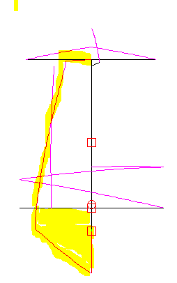
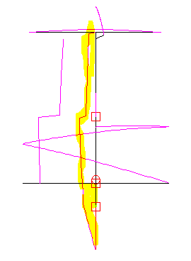
The NEC 4 wire and RF current illustration to left and below represent the same wires and tower as above left. The viewpoint has been rotated around the Z (vertical) axis to maximize the model's display of the RF current in the vertical wire and tower.
The illustration to the immediate left displays the tower current without the short between the L vertical wire and the tower. The tower current is highlighted. Note that there is far more total (integrated) current in the tower than the L. At the bottom of the tower the RF current is 4.5 amps at 1500 watts, the highest current anywhere in the antenna wires and tower, and those 4.5 amps are being driven into lossy ground. This is true even though there is no direct RF drive to the tower.
The wire and current illustration below left displays the tower current with the short between the L vertical wire and the tower. The tower current again is highlighted. Note that the amount of overall tower current is significantly reduced. Especially reduced is the current at the base of the tower being driven into the ground. The tower current at the ground is 1.7 amps at 1500 watts. The absolute value of the loss at the base of the tower will depend on the effective RF series loss at the base. Without the short the power loss will be seven times the loss with the short, the square of 4.5/1.7.
The RF current on the tower above the short is in-phase with the current on the vertical wire. Below the short it's out of phase. Compared to loop detuning of a tower and the high current within the loop, the current everywhere in the tower is considerably less than the vertical wire's 6 amps average. The vector current sum of wire plus tower is about same above and below the short. The L/FCP/tower combination has less of a weakside null than a free L. The combo at this height consistently models around 25 ohms feed Z. It will take some experience to see if that holds up in practice.
By design, the L and FCP float against the tower's RF potential at the shorting wire to produce reduced tower current below the short. At QRO this can assert thousands of volts RF between lower antenna system wires and the tower/earth. This produces the following requirements:
1) ** The Inverted L and FCP must be isolated from both coax and tower, with the single exception of the horizontal short. **
2) ** The junction of vertical wire and FCP must be fed with the isolation transformer described in
or commercial equivalent. ** A ferrite based balun or choking device will be ineffective, allowing the feed coax shield to pull the L/FCP off the design balance with the tower. The application could destroy the ferrite at QRO power levels as experienced early on by W0UCE and K2AV in applications with similar RF stress.
3) ** The support arms from the tower should be terminated in actual RF insulators. PVC pipe support arms from the tower, satisfactory otherwise, should not be the insulators per se, directly supporting the vertical wire. ** The inner surfaces of PVC pipe will gradually accumulate conductive materials from the atmosphere and weather, leading to carbon tracks and failure. Fasten an insulator to the end of the PVC by an appropriate means, and attach the wire to the other side of the insulator.
4) ** A person standing on the ground must not be able to reach the FCP or the vertical wire anywhere along its length. Touching the FCP wire while transmitting at high power could cause a severe RF burn. A minimum of 10 feet (3 m) above ground is required. **
5) ** The base of the tower must be grounded. Normal tower lightning ground and/or Ufer ground is sufficient. ** The horizontal short provides DC and lightning ground for the L/FCP via the tower. RF radials from the tower are not needed and if present, should be disconnected from the tower and separated. They do not need to be dug up. When using the horizontal short, the higher resistance at the base reduces loss by reducing current in the lower half of the tower. This counter-intuitive outcome is clearly visible in models.
Items 6) and 7) are needed to prevent tower cabling from defeating the scheme. Moderate RF resistance at the base to earth connection lowers current, thus lowering ground losses. Untreated tower cabling gives RF an easy path around that resistance, increasing current below the shorting wire, increasing ground losses from the tower below the shorting wire. This is particularly important for feed loops for crank-up towers. Installers have noted that this work can be fairly difficult, if not installed with tower construction. Often blocking and grounding is in the lower section, but not directly at the base. This is a satisfactory location for blocking.
6) ** All coax shields must be grounded to the tower at the base and up on the tower where the coax leaves the tower. Tower conductors must be bypassed to the tower with .005 uF disk caps to the tower at the controlled device and at the base. ** This includes unused conductors in cables. If not planned for later use, strip insulation from the ends of unused conductors, twist them together and ground them to the tower at both ends.
7) ** Ferrite blocking is required for the common mode paths from coax shields and control cables leaving the base of the tower. ** This prevents the RF on the tower from having a low Z path to earth, via coax shields and control cable conductors via capacitive coupling, to elsewhere other than the tower base and lightning grounds. Blocking R needed, to make the RF base-to-ground resistance of the tower the controlling resistance, depends on the number of parallel paths coming off the tower.
At 1500w NEC 4.2 models demonstrate that substituting a ferrite balun or block for the isolation transformer in this application can have disastrous consequences. Even an otherwise excellent 5000 ohms resistive ferrite block on 160 meters can have a thousand volts RF across its blocking resistance, dissipate hundreds of watts, and destroy the device, possibly setting it and surroundings on fire. A number of times in pre-publish FCP history K2AV and W0UCE did exactly that, once setting a utility building shelf on fire. If we had not looked out the window and seen smoke, it probably would have burned down.
In modeling, this design appears to support the 80/160 dual banding method for the standard L. Adding to the dual band circuitry, an inductor is substituted for the short between vertical wire and tower while on 80 meters.
This table presumes the tower is topped by a medium sized 14-28 MHz multi-band beam antenna. Data below shows the shorting wire heights for various horizontal wire and tower heights. At lower heights in the table, data for the slanting vertical method demonstrates where the two methods overlap and deteriorate in the other's range. The mechanisms creating this crossover point are not clearly understood.
The horizontal (or horizontal wire plus drooper wire) is always 88 feet in this table. This technique optimizes low angle results by keeping RF current density high on the vertical wire. See for further details.
Figures are from NEC 4.2 modeling over "average" ground. For reference, a 1/4 wave vertical over USA FCC specified commercial radial system (120 times buried AWG 4 copper 0.4 wavelength buried radials) in "average" ground produces 1.18 dBi gain.
In the table below, Tower Height, L Horiz Wire Ht, Shorting Wire Ht, are all heights above ground, not above the FCP.
| Tower | L Horiz | Shorting | Shorting | Slanting |
| Height | Wire Ht | Wire Ht | Max Gain | Max Gain |
| --Ft-(m)-- | --Ft-(m)-- | --Ft-(m)-- | dBi@Elev | dBi@Elev |
| 120 (36.6) | 100 (30.5) | 74 (22.6) | +0.16@24 | ---------- |
| 110 (33.5) | 90 (27.4) | 62 (18.9) | +0.03@25 | ---------- |
| 100 (30.5) | 80 (21.3) | 57 (17.4) | -0.11@25 | ---------- |
| 90 (27.4) | 70 (21.3) | 51 (15.5) | -0.18@26 | ---------- |
| 80 (24.4) | 70 (21.3) | 44 (13.4) | -0.39@27 | ---------- |
| 70 (21.3) | 70 (21.3) | 39 (11.9) | -0.40@29 | -0.92@24 |
| 65 (19.8) | 65 (19.8) | 32 (9.8) | -0.56@29 | -0.76@25 |
| 60 (18.3) | 60 (18.3) | 28 (8.5) | -0.89@29 | -0.75@26 |
| 55 (16.8) | 55 (16.8) | 23 (7.0) | -1.20@29 | -0.86@27 |
| 50 (15.2) | 50 (15.2) | ---------- | ---------- | -1.05@28 |
Note how results at heights 60 and 55 feet are quickly dropping off. The short's placement in modeling does not appear critical. Moving the short up or down a foot or two varies results very little. The positions posted above are the center of the usable range. For heights between listings, scale the setting between the listing above and below to better approximate the center of range.