 If one does not wish to construct their own isolation transformer, those with access to USA commerce can procure an enclosed standard size transformer from
Balun Designs.
 If one does not wish to construct their own isolation transformer, those with access to USA commerce can procure an enclosed standard size transformer from
Balun Designs.
European and western Asia sources for an unenclosed standard transformer can be found on eBay. Search on "FCP transformer".
To avoid issues discovered and solved in the decade since the NCJ article, and are required reading.
For dual- or tri-banding, or both use a 160m isolation transformer, DIY or procured.
We frequently get questions, like (IsoT*) instead of a balun, why not just any old balun? Why that toroid material, why that size toroid, why that wire, why the PTFE** sleeving? Suspiciously, these questions often occur close to a major contest involving 160 meters, with procurement now unlikely before the contest. So we will take a little aside to outline the decidedly non-theoretical reasons from the original Burn 'em Brothers -- the Crack 'em, Arc 'em, Melt 'em, Set 'em On Fire Wrecking Crew, W0UCE + K2AV.
You can skip those explanations and farther down the page.
* This web site frequently uses "IsoT" as shorthand for "Isolation Transformer".
** PTFE is often referred to by the brand name Teflon™, the registered trademark for the PTFE product line of E.I. du Pont.
Summary Answer:
♦ Smaller cores of a given material have higher hysteresis loss, more so with highly reactive loads.
♦ For a required turns count, smaller cores need smaller diameter wire that has higher RF resistance.
♦ QRP most needs lowest loss. Increase your radiated power. Keep QRP signals above distant RX noise.
♦ Unlimited lifetime at full ham QRO if neither mechanically damaged nor directly struck by lightning.
♦ Construction techniques avoid damage causing RF loss, deterioration experienced in the field.
♦ After extensive testing, highly respected balun guru W2FMI(SK) chose this core material, wire and insulation for the 4:1 stepdown balun he specifically designed for efficiency under severely reactive loads in the impedance war zone between a tuner and a highly reactive antenna. These are all described in his book.***
♦ Other materials failing, our wandering into this core/wire/insulation choice ended breakdowns, shattered and burned cores at K2AV, W0UCE, and elsewhere. Power previously lost to device heating and burning was now radiated into the pattern, improving over-the-air results. W2FMI's book emphatically confirmed the IsoT's details, explaining why it worked. The IsoT handled the wide 160m L/FCP Z range and the FCP's capacitive 130Ω feed X without core heating, realizing the goals of W2FMI's design.
Detailed Answer:
The choice of wire and insulation came at the end of a period of failed transformers subjected to 1500 watts, tough RF situations and some number of close lightning strikes at W0UCE which also took out appliances and other ham equipment. The fix to prevent blown transformers was heavy polyimide insulated wire plus standard wall #12 PTFE sleeving.
Contrary to experience with ferrite-based cores, #2 powdered iron cores wound with this combination did not fail unless they were directly struck by lightning or mechanically damaged by harsh mistreatment. Undamaged, they ran cold in FCP related applications inside 3:1 SWR bandwidth, and are still in use.
The double (heavy) polyimide insulation would not melt, but unfortunately was easily nicked in miscellaneous handling of a core wound with #14 double polyimide only. A nick in the polyimide led to carbon tracks, and burned and shorted devices. However, if the same type wire was immediately inserted into PTFE sleeving before exposure to any working or contact, it was protected from nicks and abrasion.
PTFE sleeving also increased the breakdown to 55 kVDC between adjacent wires in the winding and 27.5 kVDC between wires and the core and mounting materials, or 19.5 and 9.75 kV RMS at RF respectively**.
The wire/insulation diameter of PTFE-sleeved #14 double polyimide dictated that the T300 series toroids had the smallest inside diameter that could fit a single 20 turn laid-flat bifilar winding on the inside surface. Two or more layers of winding require a different and more difficult and expensive winding design, usually done by machines.
Balun guru W2FMI(SK), in his detailed book on baluns and ununs***, described an antenna tuner balun he designed to handle "worst cases," the war zone between tuners and antennas with wide ranges of reactance, especially deliberately non-resonant antennas such as multiband doublets. Jerry settled on a heavy and large 4 inch by 1.3 inch T400A-2 powdered iron core, and used 21 bifilar turns of the same PTFE sleeved #14 wire for his antenna tuner balun. He had done much testing to arrive at his choice of toroid core material. After our collection of failed attempts with different cores, we had happened upon and settled on the same choice and sizing of core material. And we found ourselves synchronized with the master and all his excellent research.
There were negative reactions to our using a T400A-2 core, on price and on physical size. The next smaller available diameters were the T300xx toroids. As the T300xx cores were the smallest usable inside diameter for the windings and fit in the common 4x4x2 inch plastic electrical box, we settled on and tested with the inch-thick T300A-2 core.
**See double polyimide coated wire and PTFE tubing specifications. Typical "heavy" or "double" Polyimide (14.6 kV), plus #12 standard wall PTFE tubing 800V/mil times .016 in (12.8 kV) gives a 27.5 kVDC rating for the combination. This results in 27.5 kVDC insulation between the wire and the core and environment, and 55 kVDC between wires in the winding.
***Jerry Sevick, W2FMI(SK) "Understanding, Building, and Using Baluns and Ununs -- Theory and Practical Designs for the Experimenter", pp 58-62, © 2003 CQ Communications, Inc, Hicksville, NY
We are often asked about a low power, or smaller core version for QRP since the transformers described below are probably good to 3 kW with an L over FCP.
We have steadfastly resisted downsizing. We have not and will not publish a small core version of the isolation transformer.
In the you will find downsized and miniature tuning devices listed as sources of loss. These require small wires in coils and small high μ cores for miniature transformers. Both add loss.
QRP, particularly more so QRP, benefits from reduced losses and suffers from increased losses in the antenna system. The QRO capable transformer helps QRP by reducing RF loss.
QRP ops are frequently in the situation where their signal is in the noise at the other end, the exact situation where all those recovered parts of dB's from the Loss List make the greatest difference.
Reserve miniaturized tuning items for back-packing, carry-in sites and tiny operating positions, where you require minimal size and/or weight over other considerations.
<== you are hereOn 160 meters, an IsoT wound on a T300A-2 powdered iron core exhibits some non-one-to-one impedance transformation. An IsoT wound on a T400A-2 exhibits essentially none. The "Regular" T300A-2 IsoT exhibits more than the "Heavy" T300xx. But the variation in transformation is usually absorbed without issue in the typical 160 meter pruning and tuning exercise. In many cases the leftover inductive reactance of the isolation transformer is actually helpful for overall tuning of the aerial/IsoT/FCP system.
A 160 L/IsoT/FCP sometimes gets trimmed/adjusted/tuned to 50 ohms easier with a "heavy" version T400A-2 based transformer. But the T400A-2 will not fit in the 4x4x2 inch sealing cover plastic electrical box so often used for transformer/balun housing. An alternate "heavy" version is an inch and a half stack of a T300A-2 and T300-2, minimally taped together and wound as one core. This is approaching the overall characteristics of a T400A-2 and a tight but just workable fit in a 4x4x2 inch box. This can also be done with a three-stack of the half inch T300-2. Multiple core stacks cannot be used for the field-adjustable variable turns ratio IsoT's below.
We cannot guarantee the performance benefits of a "heavy" vs. "regular" 1:1 ratio bifilar IsoT given the huge diversity of L (and other aerial wire) feed impedance from wide variation in RF free space attributes, modified by height, placement, and environment at individual stations. This subject is treated in depth in
We highly recommend you study the "Taming" section for the transformer-based step-up of a normal and efficient thirty-something ohm aerial/IsoT/FCP system resonant feed impedance ("Method B"). This produces a straight-forward 160 aerial/IsoT/FCP system well-matched to 50 ohm coax with a single device at the feed point.
To support Method B we have added an article for a robust, easily field-adjustable A:O (Antenna:Coax) turns ratio winding on the T400A-2 core
Using a larger core without adjustable turns ratio is an extra expense that may or may not render an actual benefit as a 1:1 turns ratio transformer. Other than sometimes more monkey business to get a 1:1 SWR to the feed coax, use of the standard 1:1 bifilar single T300A-2 or the equivalent double T300-2 does not in any way effect the distant end signal strength performance of a 160 L/IsoT/FCP.
When using Method B and monkeying with IsoT turns ratios, we recommend the for matching/tuning the inverted L. A 160m bifilar winding on a T400A-2 "Heavy" has less non-1:1 effect than a 3 inch, and has smaller output R increments doing single turn changes in a turns ratio.
Manipulating windings and aerial wire lengths to come as close to R=50Ω and X=0Ω at the chosen center frequency (50+j0 @ f0) is much easier on the 4 inch core. Approximately, using the removed winding turns method, the four inch changes 2.5 ohms per winding turn, and a three inch changes 4 ohms. This is due to 50 total turns of the specified wire/sleeving on the four inch versus 40 total turns on the three inch. With the T400A-2 adjustable you can usually match to 49-50-51 ohms R at center frequency.
Micrometals' identical cores for Amidon's inch-high T400A-2 and T300A-2 are the T400-2D and T300-2D respectively. The half inch high versions are labeled the same. The Micrometals cores are frequently listed on eBay.
<== you are hereMost of this section on winding an isolation transformer is based on experience, written to help you avoid things that have gone wrong for others. Purchasing a commercial version allows you to skip this section, but if you are going to wind your own, this is must reading.
* Micrometals designations for inch thick cores. Amidon and Micrometals designations are identical for the half-inch thick cores.
†† Discussion of transformers' construction and design is above in
††† Commercially available.
‡ Winding length = tight turn length times number of turns plus an extra 24 inches, 1 foot or ~30 cm each end of a wire, for lead dress and accounting for not-so-tight winding turns. Better too long than too short. For brevity, SAE length rounded up to next full inch, metric to next 5 cm multiple.
‡‡ Do not wind field adjustable IsoT's on multi-core configurations. Non-1:1 transformer windings have skipped turns. We first have to wind the 50Ω wire all the way, only then wind the low Z. Winding the low Z wire on not-rigidly-taped-together multiple cores will loosen the 50Ω turns. This causes turns not tight to the core, not parallel to adjoining turns, producing unpredictable, imprecise results. But taping the cores together tightly enough to insure rigidity during winding creates a void between cores and tape, which can't be removed. Outdoors, temperature changes in damp air will slowly fill the void with water, creating gradually increasing loss with no sudden change in SWR to signal the problem. Do an adjustable winding on the specified single core.
§§ These field adjustable transformers are specifically designed for Method B tuning (adjust far end of horizontal/drooper for X=0Ω, IsoT turns ratio for R=50Ω, measured at coax side of IsoT).
§§ Winding instructions specifically and only for field adjustable transformers will be found in You will be referred to this material after the general winding considerations below. Remaining paragraphs in this article apply to both bifilar and field adjustable windings.
Do not bother to cover the toroids with fiberglass tape. In several years of outdoor and damp indoor locations, the irregular surface of the fiberglass tape became a collection point for airborne materials. Salt, tree resin, and smoke particles, etc, could accumulate and become a dielectric and carbon track issue.
The PTFE sleeved wire should be wound directly on the bare toroid core. In addition to our experience, W2FMI flatly states in his book that fiberglass tape is not needed if PTFE sleeving is used.
Balun Designs™ excellent Installation Notes for Baluns & Ununs is required reading for installing outside transformer enclosures and project boxes, introducing the need for "weep holes". With temperature changes even a "sealed" box allows air moisture and contaminated water egress at hardware penetration points. Sometimes seal gaskets gradually fail. When sun or hot weather heats up the box, some moisture evaporates and escapes via the same penetration points, leaving contaminants behind.
Without weep holes atmospheric pressure changes or enclosure cooling can cause a relative vacuum to build up inside an almost-sealed enclosure. The vacuum slowly sucks in water and moist air around and through external connection hardware, especially the center pin of SO239 coax connectors. Over time water condenses and goes to the lower part of the box. Stories abound of opening up an SWR-gone-high outside elevated transformer box, only to get showered by an enclosure almost completely full of water.
This does not occur with weep holes at the bottom of enclosures. The cooling of the enclosure easily and slowly draws in cooler outside air. With warmer, less heavy air at the top, the cooler air slowly pulled in through the weep holes stays low. When the box heats, the inside gets a positive pressure differential. Heavier air low in the enclosure plus any condensed water are first to leave through weep holes at the bottom. In dry weather, several days of air exchange cycles from sunshine and cool nights will completely dry out the inside of the box.
Unfortunately complete and permanent avoidance of moisture and contaminant penetration by sealing electronic enclosures requires military grade moisture-proofing. This methodology, originally developed for WWII jungle and marine warfare, is remarkably complex and is not treated on this web site.
If you are winding a bifilar transformer and your core consists of multiple toroids, do not tape the two toroids together by going "around the equator". This will create a void inside the tape and between the toroids, that cannot drain to the weep holes. At some point outdoors the void will accumulate water inside the winding. This worst possible place for water will cause sneaky, gradually increasing loss.
Instead, tape the two toroids together with a perpendicular wrap at 120 degree intervals. Use narrow electrical tape plus an inch overwrap. This is just to hold them together to start the winding. After winding, the windings themselves and hold-down tie-wraps will keep the toroids together.
Avoid nicking the transformer wire's polyimide insulation or subjecting it to any kind of abrasion except at the soldering ends of the wire. Although the polyimide insulation retains its heat resistance and insulating properties well beyond common soldering temperatures, we found it easy to nick the polyimide. This was prevented by the PTFE sleeving. You may wish to do the cutting and sleeving of the wire on a carpet for this reason.
Transformers situated outdoors usually accumulate traces of moisture between the wire and PTFE sleeve. RF at a nick in the polyimide insulation can use the moisture to begin a carbon track. A nick presents a point where only the PTFE has to be penetrated for breakdown. The strategy is to require penetrating both PTFE and the polyimide for breakdown.
Do not use any kind of lubricant on the wire to assist sleeving with PTFE tubing. PTFE is already very slippery. It is possible to push 20 feet of #14 heavy polyimide wire inside #12 standard wall PTFE tubing. Some lubricants will actually make it harder to insert the wire. The lubricant can also be of a composition that deteriorates or introduces loss. To avoid digging into the PTFE during insertion, burnish the wire's insertion end-cut with a fine fingernail file or sandpaper until it is smoothly rounded without sharp edges. When done filing be sure to wipe off any grit or other residue from the wire's insertion end.
Before you cut the wire or tubing, measure the PTFE tubing twice and only then cut to size. To reduce friction, gently straighten the wire just as it is being pushed into the PTFE. Push the #14 polyimide wire all the way into the #12 standard wall PTFE sleeve until the far ends of wire and tubing are even. Then cut the near end of the wire even with the near end of the tubing. PTFE sleeving is now protecting the polyimide insulation from nicks. Do this for two wires, each wire at the length for your choice of core(s) in the table above.
Do not use a marker pen to mark a winding wire as marker ink does not stick to or penetrate PTFE. Even permanent marker ink wipes off as the wire is handled during winding, resulting in one or both ends of the winding unmarked. It's then very easy to unwind, cut or connect the wrong wire. Getting wires flipped on one end of the winding changes the isolation transformer to a weak choke. It will add loss to the system by driving power down the feedline shield. It will considerably affect impedance match settings, but otherwise may seem normal. The instructions have you check for a flipped ending pair, but if you have already trimmed wrong leads and wired wrong leads to connectors, you may have to splice wires to repair. Worse, you might have to pull all the wires off the core and completely start over.
If you are winding a field adjustable IsoT, the long winding is wound first, and the short winding next, skipping over selected turns in the long winding. Jump now to specific procedures for Afterward you will be referred back below for connecting and testing.
If you are winding a 1:1 bifilar IsoT, in case you later decide to tune the aerial/FCP with an improvised turns removal Method B: On the winding wire to be connected to the coax connector mark both ends and the center and the 1/4 and 3/4 points with "flags" of tape, five flags in all. Later, if you don't flag, it will be very easy to accidentally trim the wrong wire modifying the turns ratio for Method B impedance and ruin the transformer, forcing a rewind or rewire or both.
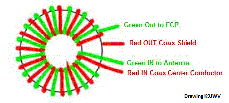
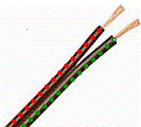 If you are winding a 1:1 bifilar IsoT, pair the wires. Think of it as exotic zip cord. Although it is not required, it is easier winding (and looks better) if you tape the wire together roughly every four inches (100mm) with narrow tape. Ordinary width electric tape can be cut in half lengthwise with scissors for this purpose. Wrapping with a turn and a half around the wire pair is sufficient. Once the winding is on the toroid(s) there is no stress on the tape.
The wire lengths in the table include generous lead lengths to reach various points in a project box. Better too long than too short.
One flagged wire end goes to the coax center conductor connection, the other flagged wire end goes to the coax shield connection. If you shorten a flagged wire to clean up inside the project box, immediately reflag the wire. The flags will be essential if you later want to change the turns ratio. Since a method B shortening will reduce turns on the FCP/Antenna winding, having the flags on the Coax winding will avoid messing with flags on a method B turns adjustment.
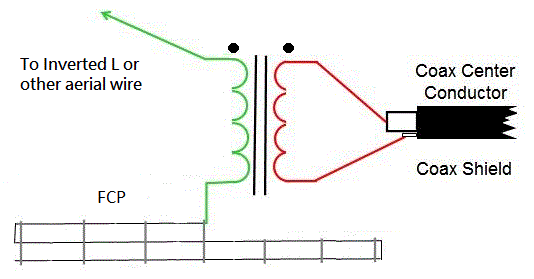
<== you are hereExtremely important: After winding and preparing to make connections, make sure your connections will follow the schematic below.
This section and polarity marks on IsoT schematics are new on the web site with V.2019.03.15.
Always connect an aerial wire, FCP and coax to an isolation transformer per the drawing at left.
IF 1) you know or suspect a Balun Designs IsoT has been modified from its original wiring,
OR IF 2) you are using an IsoT of unknown origin or manufacture, with or without enclosure,
OR IF 3) you are directly wiring any IsoT into an installation or enclosure, either a user-wound IsoT, or a commercially wound IsoT removed from or without an original enclosure,
THEN perform all four tests below in
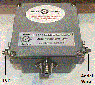
All unmodified enclosed Balun Designs isolation transformers are identically wired internally, with identical external connections.
Balun Designs isolation transformers sold January 15, 2019 and later have "FCP" and "Antenna" labels at the correct 1/4 inch stud terminals. Always connect a Balun Designs isolation transformer per labels next to the 1/4 inch studs.
If you have an older unmodified Balun Designs isolation transformer with no "Antenna" or "FCP" stickers next to the 1/4 inch studs, then:
Hold the transformer enclosure with the cover side (four screws) facing you, coax connector facing down. Connect the aerial wire to the right side stud and FCP to the left. You might want to add the markings "FCP" and "ANT" with a permanent marker.
Disclaimers: Balun Designs™ is a highly valued commercial resource, providing a source of professionally constructed transformers described on this web site. They are, however, not responsible for the design of said transformers, not responsible for knowing or explaining how to use them. Balun Designs warrants their workmanship and that the 1142s uses the same design and materials specified on this web site for those winding their own transformers.
This web site is not a commercial enterprise. K2AV receives no royalties or compensation from any source for use of the antenna and transformer designs. The content of this site is published without charge for the furtherance of amateur radio and the benefit of the readership.
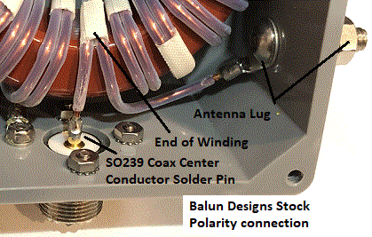
1) There is no ohmmeter test to verify winding polarity. It must be done visually. The cover of an isolation transformer enclosure must be opened to verify.
Examining whichever end of the bifilar or parallel wire winding can be clearly viewed, §§
EITHER 1a) Verify wires intended for or wired to the coax center conductor and aerial wire make up one end of the bifilar or parallel wire winding. Photo left illustrates the aerial wire and coax center conductor end of a stock Balun Designs bifilar isolation transformer winding.
OR 1b) Verify the two wires intended for or wired to the FCP and coax shield make up one end of the bifilar or parallel wire winding.
§§ In the case of non-1:1 turns ratio transformers, the wires are not bifilar. Instead the two wires will form a parallel wire winding which includes sections of bifilar winding, one winding wire skipping turns at equal points around the core and possibly one or the other wire skipping a turn(s) at its ends. See the winding diagrams for field adjustable non-1:1 IsoT's for specifics. The wires to the aerial and the coax center conductor should be paired at one end or become paired on the core in a few turns. The wires to the FCP and the coax shell should be paired at one end or become paired on the core in a few turns.
2) Place ohmmeter probes on the wires intended for or wired to the FCP and aerial wire connectors. You should see a dead short.
3) Place the ohmmeter probes on the wires intended for or wired to the coax shield and coax center conductor connectors. You should see a dead short.
4) Place ohmmeter probes on the wires intended for or wired to the FCP and coax center conductor connectors. You should see an open.
If one or more tests fail, you have either a wiring designation error to resolve, or an outright wiring error to correct before installation. Getting wires mixed up is the most common failure related to a user-built or directly-wired or modified isolation transformer.
Short Answer:
We all wish we had figured out the reverse connection issues years ago. It's particularly obvious now that normal and reversed connections do not behave the same since we now have 2 port VNA measurements and other results for normal and reversed connections.
The simple and cruel answer to what to do: If your existing FCP/aerial wire connection is reversed, and you suspect some performance degradation, or it simply bothers or worries you, then you can un-reverse it and do the tune-up work over again. There is the suspicion that it will be easier to tune with the normal connection but no guarantees, yet. There is the suspicion that un-reversing will remove some degree of loss, or reduce local noise on the coax shield getting back into the RX via the transformer, but no guarantees, yet. We simply lack enough accumulated multi-site testing and experience in 03/2019 to definitively list probable results of un-reversing.
Really Long and Detailed Answer:
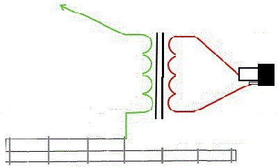
The schematic at the left was W0UCE's original 2009 basic drawing of aerial wire, isolation transformer, FCP and coax connection, still embedded in this web site's home page. Little has changed in nine years of publishing, no changes to the schematic per se. Polarity dots were added 03/2019 to explicitly specify the polarity implied by the presentation.
Many simply wound and connected the transformer per the drawing. They read it to mean that the center conductor and aerial wire are supposed to be on the same end of the bifilar winding. And so they conveniently, if unknowingly, avoided the now-known issues with reversed connections.
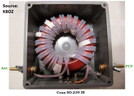
Pictured left, K8OZ's isolation transformer in the NCJ article clearly shows the correct polarity connections with marked aerial wire and FCP connections. In 2010 Jim would not have received any instruction to that effect, other than W0UCE's drawing. Likewise K9JWV's earlier drawing of the winding on a core necessarily had the same origins.
K2AV admits to a vague memory of issues taming the first isolation transformer at W0UCE. K2AV couldn't get it to work correctly until he "tripped over" a particular wiring that behaved. This solution, however not understood then, explains Jack's original drawing. To make the drawing, Jack went out to the box and traced the wires.
In 2010 we were a long way from the personal knowledge to understand that problem. We were also a long way from owning the needed equipment and programs to analyze and solve the problem. Some of the equipment became available only recently at less than military prices.
Until 2018 we had no reports of issues with reversing the FCP/aerial wire connection. Then we had a few reports that touching the SO239 shell on the isolation transformer made a change to the SWR. And we were a little slow to figure it out.
In our defense, ever since the FCP and isolation transformer were publicized, including prior to the NCJ article, installers often reported that the isolation transformer eliminated the SWR change often seen touching the shield when using a balun in place of the transformer.
Over time the suspicion grew that reversed antenna/FCP connections changed how the L/FCP tuned up. This proved difficult to chase down in the field once a given installer had his L/FCP up, tweaked, working contests and DX. Understandably, satisfied users were reluctant to take apart a working installation for research testing. The conversation usually included some variation on "If it ain't broke, don't fix it."
When K2AV put up his "New" inverted L in fall 2015, he used an on-hand Balun Designs 1142s instead of winding a new transformer. It had no Ant or FCP stickers marking the studs. It was connected per-the-web-page-diagram without any conscious intention by K2AV.
The FCP wire came through the shed wall on the left and the inverted L vertical wire on the right. The FCP was on the left because, happily, two big tree trunks lined up to suspend the FCP directly over a corner of the shed needing only a center post mounted to the shed facia board for a nicely uncluttered layout. Compliance with the Loss List's FCP specification for a ten foot diameter tunnel clear of dielectric material required only trimming a few branches off two backyard trees. Just what the doctor ordered.
The 1142s was mounted to a plywood "breadboard" on two adjacent wall studs between where the two wires came through the wall, using the screw-down tabs on the back of the box. Thus the cover with four screws faced the viewer. The coax jack pointed down toward the floor where the coax went underground and out of the shed. Thus the box cover with the screws faced the viewer with the coax jack down, the FCP connected to the left stud, the aerial wire to the right stud.
Here the reader might notice compliance with instructions above for "Connecting Unmodified Stock Balun Designs™ Isolation Transformers". Blind luck, or the angels looking out for K2AV.
Had the FCP been routed on the right side of the shed, K2AV's transformer hookup would have been reversed, and we may have discovered the issue in 2015.
The "new" 143 foot L over FCP yielded results with the expected approximate readings and a feed R in the low thirties. Later, when RBN readings from the new L/FCP were better to the west coast and Europe than from the old, there was only a great sigh of relief that the new power lines up on the service road hadn't ruined the only good 160 inverted L site on the property.
Then in fall 2018, partly to analyze the now and then reported SWR change issue, K2AV purchased a cigarette-pack-sized portable two port vector network analyzer, the Mini Radio Solutions "miniVNA Pro2". He also bought a Surface Pro laptop to replace the household's vintage 2004 memory-starved and stuck-at-Windows-XP Compaq laptop.
The VNA is powered by a rechargeable internal lithium ion battery and uses Bluetooth to talk to a Java VNA driver program running on a Windows computer or Android phone. The Surface Pro, with internal Bluetooth capability, functions as a tablet by unsnapping the keyboard/cover, making the VNA/PC combo very portable and wonderfully handy for antenna tweaking.
Critically, the internal-battery-powered, isolated-by-Bluetooth VNA could measure the L/FCP with the isolation transformer primary winding as the only attached metal while testing the wiring reversal. Stand-alone two port tests measured the common mode leakage path of a "stock" Balun Designs 1142s/160 isolation transformer. Reflection mode tests checked K2AV's FCP/IsoT/L feedpoint for common mode effects by attaching and detaching the feedline shield using both normal and reversed winding.
To check the effects of introducing a common mode signal, K2AV used his L's isolation transformer, now a hand-wound version after giving the 1142s to VP5M. He was somehow still using the correct normal FCP/Aerial connections. He ran VNA scans in reflection mode at the coax jack to record characteristics without any common mode voltage. He then attached the feedline shield with a clip lead to the coax shield of the VNA/transformer connection, introducing common mode voltage to the combination. The common mode voltage shifted the X=0 point lower. The shapes (not the frequency position) of the R and X curves remained the same, shield attached or not.
When the FCP/Aerial connection was reversed, attaching the feedline shield significantly changed both R and X curve shapes. The X=0 point shifted upward substantially, indicating a significant feedback effect.
K2AV then tested a brand new, bought for the experiment, Balun Designs 1142s/160 isolation transformer at 1.825 MHz to measure isolation, R, X and |Z| of the common mode leakage path, with normal and reversed antenna connections.
With the VNA in transmission mode, VNA port 1 output was fed to the 1142s antenna side 1/4 inch studs with clip leads so the port 1 high side and ground connections could be flipped for normal and reversed. The coax side SO239 was terminated in an enclosed, shielded 50 ohm termination. The VNA port 2 input center conductor was connected to the external shell of the termination with a clip lead to sense any leakage from the transformer to the outside of the termination shield (common mode leakage path). The results follow:
| Tested Unit: | New Balun Designs 1142s/160 | |
| Field Strength Test: | Using 15 Watts to Tuner + Coax | at K2AV (Discussion below) |
| ATR-30 Tuner Set For: | 50 + j0 on AIM4170 in Shack | at K2AV (Discussion below) |
| Leakage Path Blocking Test | Normal Wire Connections | Reversed Wire Connections |
|---|---|---|
| dB Isolation | 43.6 dB | 26.5 dB |
| Inductive Reactance (X) | 5.23 k Ohms | 2.07 k Ohms |
| Resistance (R) | 14.2 k Ohms | 240 Ohms |
| Impedance Magnitude |Z| | 15.1 k Ohms | 2.09 k Ohms |
| -------- | -------- | |
| Field Strength Test | ||
| Volts/meter at 125 Feet | 1.15 V/m | 1.14 V/m |
| -------- | -------- | |
| ATR-30 Tuner Settings | ||
| Trans/Ant/Inductance | 2.0 / 4.5 / 18.0 | 2.5 / 3.2 / 18.0 |
| Resonance, Tuner Bypassed | 1.817 MHz | 1.838 MHz |
Note the large difference in the R values of the common mode leakage path. With reversed connections a small unfortunate series capacity would leave an R of only 240 ohms blocking induced TX power on the coax shield. This would cause a hard-to-predict voltage feedback from the aerial wire that varied considerably with changes in frequency. This explains the shape changes in the R and X curves using reversed wiring when connecting the coax shield.
Reversing the connections also weakens feedline common mode noise blocking by 17 dB. Common mode noise can enter the shack on feedline shields and be blocked with various devices. But common mode noise can also leak into the antenna itself. Once into the antenna circuit, the noise cannot be separated. The normal connection's 43 dB blocking of common mode voltage explains a common story that changing to an isolation transformer made the antenna quieter on RX.
If you have already successfully matched your L/FCP with a reversed isolation transformer connection, you may not wish to change the connection unless you think you have issues of some sort and you are prepared to redo your match to the L/FCP. If you are having difficulty matching and are reversed, then you have nothing to lose -- change to the normal connections and proceed from there.
To measure field strengths, K2AV used a continuously variable ATR-30 tuner and an AIM4170 VNA in the shack to present exactly 50+j0 to the transmitter for both the regular and the reversed connections. Transmitting at 15 watts, he measured field intensity 125 feet from the vertical. The measuring instrument was an in-certification lab-calibrated Potomac Instruments FIM-41 professional field intensity meter. The field strengths are reported in the table above.
Contrary to expectations, reversing the connections did not produce significant field strength loss. However, this single result at K2AV should be considered preliminary and possibly not representing the majority.
There may be a situational reason for the very small reversal loss at K2AV. The exposure of K2AV's 160/80 hardline shield to induction from the aerial wire is only 25 feet with 8 feet in buried conduit. The coax shield is grounded at the house entrance. There's 12 feet laying on the ground. Then the 8 feet in buried conduit and five feet up to the transformer. A more common 80 or 100 feet of RG-8 style coax laying on the ground outside the house might produce a much higher interaction, and loss.
In the field it will be very hard for most stations to measure loss caused by a reversed connection, even a significant loss. It's tricky. To properly measure requires an accurate power meter, a continuously variable tuner, an RF analyst to display the impedance (R ± jX) presented by the transceiver side of the tuner, and an accurate, stable field strength meter. Also, to avoid corrupted readings, one needs a working knowledge of the various circumstances that can degrade field strength readings.
Reversing connections probably produces two obviously different impedance (R ± jX) readings at the shack side of the transformer. See the last category in the table above. It is probable that a reversed connection has significantly hampered tuning and matching for some installers.