Click here for a year's evaluation of 40m on the Trident L versus a proven effective 40m inverted V.
[For discussion, azimuth patterns and text below use "up" as North and the intended 160m pattern maximum. The optimum direction looks from the far end of the horizontal toward the bend. Real life maximums will rotate with actual horizontal wire orientation. To obtain patterns below in reality, with North at the top of the pattern, the horizontal wire would have to be North-South, with the supported bend on the North end, as at K2AV.]
Important Warning: The trident wire's angle and spacing from the horizontal wire, straight line shape and length are critical to its 40 meter pattern shape. Unfortunately, small changes in the trident wire make large changes in the pattern shape. Do not adjust the trident wire in any way to tune R, X, or SWR.
Note: If you only want to add 80m to a 160 InvL/IsoT/FCP see To add 80m only to the L/FCP, you will not need the Trident wire and its extra 40m switching and matching circuitry.Note: When the L's bend is supported by a tower, this 40m extension to the 160+80 scheme suffers significantly reduced North coverage (as defined for discussion purposes above) plus other pattern degradation. No solution is currently known, though certainly much time has been spent looking.
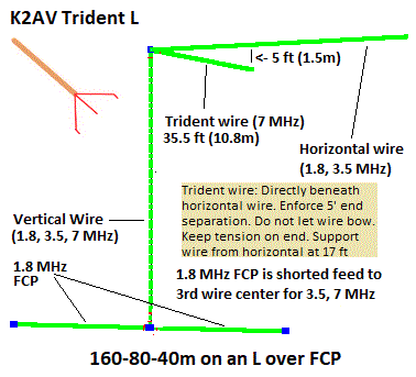
In 2011 K2AV started looking for a way to add 80m and 40m to the 160m L/FCP. An L/FCP was already using scarce small lot resources: Coax run, L wires and FCP, antenna supports, and especially the ground space already taken up by the 160m L/FCP. Ideally, existing 160m resources could be made to work well for 80m and 40m. To pass muster, those RF patterns had to compete satisfactorily with an 80m Inv Vee and a 40m dipole.
Adding 80 and 40 brings complexity to the feedpoint and the shack, often requires purchasing a few expensive components. But the three low bands in one setup sharing scarce property resources could be worth it. New components can be bought. But most hams cannot increase their acreage for a hobby. A solidly performing Trident L replacing old antennas could release space to add new or improve remaining antennas.
The 160m L used on 80m became an end-fed half-wave, an efficient single wire antenna proven to K2AV for decades in the cauldron of year-round short- and long-haul 80m traffic nets. The hurdle was how to use the 160 FCP as an 80m counterpoise. The solution added a high voltage vacuum relay short from FCP feed to FCP third wire center for 80m operation. Then we added 80m high-Z matching at the feedpoint. 160+80 on a 160m L/FCP is now out there and working well.
The 160 L/FCP as a 40m aerial was a much harder problem. But it wasn't the counterpoise. The FCP short for 80m also worked for 40m. The problem was the RF pattern. Over a decade, K2AV ran EZNEC on thousands of unsuccessful designs to find that solution. Until 2019, that quest was far and away his most frustrating antenna modeling no-solution.
The search was complicated by five 40m requirements which all had to be satisfied at the same time.
(1) The strong and weak directions of the 40m pattern must match 160m. The installer already picked his least important direction when he was planning for his 160m L. That was not an 80m issue because the L as an end-fed half-wave is fairly omnidirectional, a proven excellent all-around local and DX single-wire antenna.
(2) To build up the N quadrant, gains NE and NW need to be equal to or better than E and W. This contrasts with dipole maximums E and W, already dropping -3 dB at NW, NE, SE and SW, and to -10 dB and more N and S. The solution must redistribute enough power from E and W pattern lobes to NE and NW so they are not dropping off.
(3)The solution's vertical polarization needs to cover N well enough so it's not a hole in the coverage. Vertically polarized energy heading below the horizon will not be reflected and thus be lost, so the pattern to N probably has to have less gain than E or W.
Using the 160m L on 40 "as-is", without an additional wire, had a lot of loss and an awful pattern decisively failing (1), (2) and (3).
(4) Any 40m aerial wire addition to the bare 160 Inverted L needs to be as mechanically simple as possible, ideally just one extra wire somewhere.
(5) The addition needs to retain 160/80m efficiency and patterns. Moderate jiggling of feed impedance and needing to retune 160 and 80 is acceptable to a point.
If these five requirements were not enough, the 40m pattern and gain were extremely sensitive to the added "Trident" wire's length and its relationship to the horizontal wire. This in turn extremely narrowed the range of workable dimensions, which also explains the long time to discover the solution to (1)-(5).
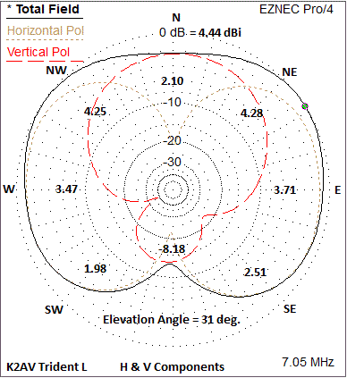
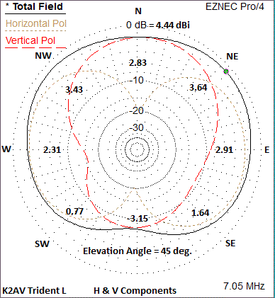
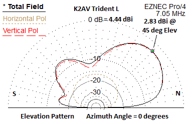
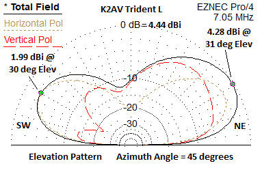
Tops of the azimuth patterns are north. The horizontal wire is pulled away from the L's bend toward the South. FCP at 10 feet (3m), 55 feet (~17m) of vertical wire, 88 feet (~27m) of horizontal wire. This is a K2AV backyard, ordinary, medium-size L/FCP, not a huge one. Various details of the Trident wire are discussed below.
The first pattern contains the overall maximums for elevation and azimuth, which are approximately northeast and northwest at 31 degrees elevation. A thirty-ish degree elevation maximum is a very typical aspect of a 40m dipole at 65 feet elevation. This is the Trident wire radiation acting in a dipole manner, supplying the E/W horizontally polarized component of the pattern (tan short-dashed graph line).
The vertically polarized component (red long-dashed graph line) radiates from the Trident wire and the top half of the vertical wire. They have significant cancellation to the South. This fills out the "dipole hole" to the North, adding to the horizontally polarized at NE and NW, for the maximums. This supplies three good directions, matching the W-N-E best in the 160m pattern. At K2AV, in North Carolina, NE and NW are the two major distance contesting directions, Europe and West Coast USA. Coverage down to SE and SW is provided from the dipole behavior of the Trident wire.
At 45 degrees takeoff, signals are increased N to form a near perfect half-omni W-N-E. The South dipole hole seen at 31 degrees elevation is greatly reduced. From K2AV, this keeps Florida, Central America and the Caribbean in play, all high angle targets.
In throwing up a wide range of models to discover a solution for the requirements above, the patterns did not give gradual hints of good things to come when moving in the right direction. This pattern is hidden from view in a string of models until you're almost right on top of the solution. It's a balance of two contrary tendencies that come to a sharp null against one another. That's K2AV's explanation for the time it took to find it. The Trident L is a solution that wants the Trident wire exactly like it wants it. There are support requirements for the Trident wire that probably can't be ignored. A big droop in the Trident wire blows the pattern.
Starting with a dual-banded L/FCP, the three band Trident L makes two additions and avoids a third.♦ In the air, the Trident L adds a single 35.5 foot (10.82m) wire to the L's bend, the "trident wire" which stretches beneath the L's horizontal toward the far end. The end of trident wire is suspended 5 feet (1.52m) below the horizontal wire.
Important Warning: The trident wire's angle and spacing from the horizontal wire, straight line shape and length are critical to its 40 meter pattern shape. Unfortunately, small changes in the trident wire make large changes in the pattern shape. Do not adjust the trident wire in any way to tune R, X, or SWR.
♦ In the matching circuitry, the Trident L adds a 40 meter relay disconnecting the 80m capacitor for 40m operation and connecting a set of 40m taps to the coil.
♦ Avoiding a change to the FCP, 40m uses the 80m setting of the FCP shorting relay. With 40 meters added, the FCP shorting relay states are now (1) FCP not shorted, 160m and (2) FCP shorted, 80/40m.
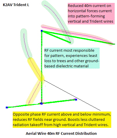
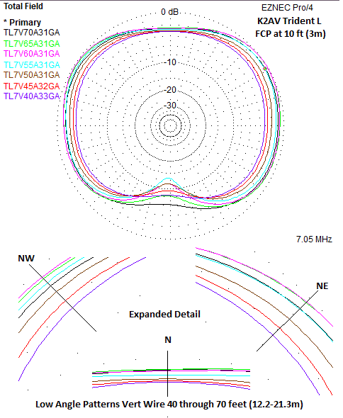
There are some very interesting aspects to how the Trident L works. They are seen by examining the 40m currents on the Trident L.
♦ The electrical length of the trident wire plus the vertical wire, taking interactions into effect, exceeds a half wave. With a 55' (16.8 m) vertical wire there is a voltage node 2/3 of the way down. The current minimum at the voltage node is a current phase reversal point. The fields from the bottom third of the vertical are equal and opposite the fields from the middle third. These opposite fields leaving parallel to the ground will largely oppose each other in the near field, raising the intensity of fields from other parts of the aerial.
♦ Thus more far field energy will depart from the trident wire and the top third of the vertical. This in turn reduces dielectric loss to nearby trees and ground clutter. The tree and clutter dielectric loss cannot be computed in a NEC model. But the loss effects of trees and ground clutter are well documented and minimizing that loss will contribute to the Trident L 40m performance, especially at low angles.
♦ On 40m the entry impedance of the horizontal wire is high. The trident wire's is low because it's close to resonance. So the division of current at the bend will heavily favor the trident wire. However, the trident wire induces the horizontal with opposite phase current. How much induction depends on the length and angle of the trident wire to the horizontal. There is a combination of trident length and angle where the reverse current along the horizontal wire reduces the E/W dipole fields displacing that energy to SW, NW, NE, and SE, creating the near omnidirectional pattern favoring NW and NE.
On 160m and 80m the current division at the bend has a choice between a relatively friendly 88 feet and a way too short 35.5 feet. The trident wire carries very little current below 40m, and so does not force re-engineering 160 or 80. In reality there most likely is just a small change of frequency where X=0.
♦ The last illustration overlays low angle patterns for vertical wires 40 up to 70 feet (12.2 - 21.3 meters), in 5 foot (1.5m) intervals. The interplay discussed above causes 70 to actually fall behind 55 toward the NW and tie 55 to the NE. 60 and 65 are tied for high signal SW through N through SE. That is a best 4.9 dBi to NW and NE and 2.4 dBi to N.
At this point we do not have a "best" procedure to go directly to Trident L or from an existing 160+80 setup. We will need people's experience for that. We will keep this section continuously updated as issues are discovered and corrected.
Important Warning: The trident wire's angle and spacing from the horizontal wire, straight line shape and length are critical to its 40 meter pattern shape. Unfortunately, small changes in the trident wire make large changes in the pattern shape. Do not adjust the trident wire in any way to tune R, X, or SWR.
Note: The repeated warning is intentional. You can lose 3 or 4 dB in a given direction(s), possibly more, with no way to detect the change other than reduced performance. And part of your benefit is lost. Especially for this upgrade, for best results strictly comply with the specifications.
Initially, pre-Covid, several of these were going up in the Raleigh area, Raleigh because we could talk to each other at club meetings, and take a short drive to manually help each other. The pandemic essentially canceled such mutually supportive activity and little progress has been made adding new local sites. However evaluation has continued at K2AV with good result.
See the 2021.04.15 evaluation for particulars of the Trident L versus a proven effective 40m inverted V.
Available Trident L Plot File Downloads:
If you have EZNEC, or other display capable programs not documented here, 3D PF3 plot files allow viewing any elevation or azimuth slice on a single specific antenna while rotating azimuth and/or elevation. 2D PF files contain a single elevation or azimuth slice on a single specific antenna, which can be overlaid with other 2D plots for comparisons. Plots' nominal desired direction are centered on N in these plot files for discussion purposes.
To view a downloaded PF3 or single PF:
♦ Start any level of EZNEC, version 6.0.23 or later, including the free demo version.** You may wish to consult the excellent built-in EZNEC help files if you have never used EZNEC before. The free demo version includes the full help.
♦ Click on "View" in the main window menu bar.
♦ Click "Traceview." Main EZNEC will drop, starting a Traceview window and bringing up a "Select Primary Trace" window.
♦ Set the "Select Primary Trace" window to your download directory.
♦ Click on the PF3 or PF file you wish to view.
♦ Click "Open". When that is finished,
♦ Click "FF Plot" to the left in the Traceview window. The EZNEC 3D Plot window will come up and function normally.
♦ To view additional plot files, Repeat the "Open" and "FF Plot" steps using the left side buttons in the Traceview window.
To view 2D elevation and azimuth slices with polarization traces from a PF3:
♦ In the 3D Plot window click on "Show 2D Plot". The 2D Plot window will start.
To view multiple downloaded PF files in overlay mode for comparison:
♦ Start any level of EZNEC, version 6.0.23 or later, including the free demo version.**
♦ Click on "View" in the main window menu bar.
♦ Click "Traceview." Click "OK" on the "End normal program" warning. Main EZNEC will drop, starting a Traceview window and bringing up a "Select Primary Trace" window.
♦ Set the "Select Primary Trace" window to your download directory.
♦ Click on a PF file you wish to view. This trace name will display at the top of the list and will be the black trace in the default color pallet. We suggest you pick the trace at the center of your interest in the list.
♦ Click "Open" in the "Select Primary Trace" window.
♦ Click "FF Plot" to the left in the Traceview window. Traceview will present the first PF in the 2D Plot window.
♦ For additional PF files you wish to overlay:
♦ Click "File" in the Menu Bar of the 2D Plot window.
♦ Click "Add Trace" in the dropdown menu. It will bring up the "Add Trace" window. If needed, set it to your download directory.
♦ Double-click the .pf file you wish to show. The 2D Plot window will display the trace in a color code matching an upper left listing of PF file name minus the suffix.
♦ Repeat the "File", "Add Trace", double-click for the rest of the .pf's you wish to compare.
The filenames in the 2D Plot window listing are also seen in pink lettering in the web site's blue download button listing. The white text in the download buttons serves as your indexed description explaining the particulars of the plot. You can keep that up in a browser window next to the 2D Plot window. The files have much of the description encoded in the file name, which may become familiar.
When you are finished viewing altogether:
Click "File" on Traceview window menu bar, then "Exit". You will need to restart EZNEC if you have further work.
** Obtaining or Upgrading EZNEC:
Behavior of Traceview from EZNEC before v6 with externally supplied PF and PF3 files generated in EZNEC v6 has not been tested by us.
In v6.0.23 W7EL graciously added code to present in overlay a .PF collection that does not start the usual way with a trace already generated in the currently running EZNEC session. These instructions take advantage of the new capability. Later, retiring from active work on EZNEC, W7EL published a free, final V7. If you are not running 6.0.23 or later, we urge you to update your EZNEC to the free final version EZNEC Pro/2+ V. 7.0. at EZNEC.com.
Differences with 6.0.22 and earlier will not be supported in our documentation. Instructions above may work in older versions, but not guaranteed.
If you do not have EZNEC you can download the free EZNEC Pro/2+ V. 7.0 final version from EZNEC.com. EZNEC Pro/4+ V. 7.0 was only available to existing Pro/4 V6 customers until W7EL's retirement. It can no longer be purchased. NEC4 and NEC5 will have to be purchased from Lawrence Livermore National Laboratories, and use shells other than Windows EZNEC.
K2AV continues to use EZNEC NEC 4.2, shelled in EZNEC Pro/4+ V. 7.0.1. K2AV is an EZNEC user since 1997, EZNEC/4 (Pro/4) since 2002.
(2021.04.15) Evaluation of Trident L 40 Meter Performance
We are moving the Trident L to "verified" status. We assume that field implementation will continue to provide surprises, issues to fix, improvements to add, particularly in physical implementation, but there is no longer any doubt of effective operation at K2AV.
The Trident L goals, 40m added to an existing 160/80 dual band L/FCP, were to 1) perform comparably to a dipole or inverted vee with a feedpoint at or about the height of the L/FCP horizontal at the bend. 2) not degrade or cause large retuning of 160/80 operation. Rough similarity of overall signal strength of the two was predicted by the modeling, but needed verification. Other prerequisite goals regarding the Trident L's modeled radiation patterns were deemed met prior to this evaluation, see the main article below.
K2AV's tower has a 40/20 inverted V with apex at 55 feet, broadside to 145°/325°. Europe is off the northeast end. The Trident L vertical wire (with horizontal to the south)is located 165 feet bearing 155° from the tower.
The Trident L horizontal pulls away from the vertical wire to 177°. This is close enough to due north-south that patterns in this article for an inverted L over FCP at 10 feet, aerial wire rising 55 feet and 88 feet out do not need azimuth rotation to represent K2AV QTH.
The Vee feedline has 265 feet of LDF4-50A shack to tower switch plus 60 feet of BuryFlex up the tower. The L has 82 feet of LDF4-50A from ATR-30 tuner in shack to isolation transformer (IsoT). Measured loss (AIM 4170) for the Inverted Vee total coax at 7 MHz is 0.7 dB, and coax from tuner to IsoT is 0.1 dB, matching extrapolation of manufacturers' loss tables.
1) 160/80 tuning:
The 160 center retuning, after adding the Trident wire, removed 8 inches from the main horizontal, with no change to the R value at IsoT output. 80 meters was not noticeably changed, though this was after some otherwise needed rebuilding of the 80m tuning circuit.
2) Performance Comparison:
The testing setup was both antennas connected to a K3 via Ant1 and Ant2. Tapping ANT switched which antenna was on the S-meter, the K3 display showing "ANT1" or "ANT 2" for easy comparison. Ant1 was always the Trident L and Ant2 the Vee.
The K3 was equipped with the second RX, connected in diversity mode to the antenna not being used for TX (using KAT3 option connecting the "not-transmitting" antenna to the second RX). Listening with headphones placed the Trident in one ear and the Vee in the other.
Tapping ANT would reverse the audio "sound stage" with the displayed antenna always in the left ear.
The diversity arrangement allowed working various contests, the weekly CWT's, CQ and ARRL DX, Sweepstakes, etc, while simultaneously listening on both antennas to all stations heard and worked.
Significantly different signal strengths would move the apparent sound source to one side or the other. Fast QSB conditions would often vary between the two causing the apparent source to quickly move left or right. RF, AF gain and AGC settings were set to eliminate unequal gain to the headset.
The most striking performance difference between the Inv Vee and Trident L was listening to Europe. The Vee was a deliberate 55 foot height, 100° V angle, broadside to NW to maximize results in the ARRL Sweepstakes and other USA/NA contests. So some advantage to the Trident L toward Europe was expected, but not to the extent heard. Europe had usually been workable on the Inv Vee, since a 100° Inv Vee doesn't have an end null nearly as deep as a similar height dipole. The Trident was usually an S unit better than the vee on Europe, sometimes with weak European signals audible on the Trident and not on the vee.
Receiving South Africa was usually equal. This was easily heard on weak signals in the noise. Carribean stations were usually quite loud on either antenna, an unexpected strength for the Trident L.
During daytime, sometimes the vee would be better to New England. Daytime W to NW to N the Vee was always louder to midwest states, doubtless due to the increased NVIS with the deliberate 55 foot apex. At night which was louder in this range varied, often trading QSB dips back and forth. Signals from Arizona, Utah, southern California, etc. tended to be similar, while northern California, Oregon, Washington, British Columbia were often better on the Trident L.
An August afternoon RBN spot comparison (2145Z), running 1500 watts, showed results to be expected from the patterns below. Averages of US RBN readings with a spot on both antennas were 30.0 for the Trident L and 28.6 for the dipole. Given the typical QSB, the difference of 1.4 dB is probably not statistically significant.
Accordingly we conclude that the Trident L performance goal of rough 40m equivalency to a good dipole or inverted vee has been accomplished.